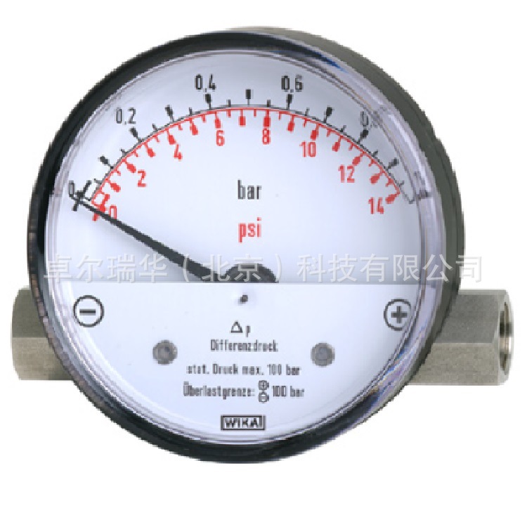
WIKA 700.01 700.02 差压表
带有磁铁活塞 可选项隔离膜 表径80mm
Differential Pressure
Gauges
Model 700.01, With Magnetic Piston
Model 700.02, With Magnetic
Piston and Separation Diaphragm


Fig. top: Model 700.01
Fig. bottom: Model 700.02, with
separation diaphragm
Applications
Filter plants
Pump monitoring
Cooling circuits
Pipeline systems
Special
Features
Differential pressure measuring ranges
Model 700.01: from 0 ... 400 mbar to 0 ... 10 bar
Model 700.02: from 0
... 160 mbar to 0 ... 2.5 bar
Sturdy and compact system case made of
stainless steel
High working pressures (static pressures), optionally
100,
250 or 400 bar (Model 700.02 to 100 bar max.)
Overpressure
safe either side to maximum working pressure (exception for Model 700.02: see
table page 2)
System and/or case of indication may be changed
locally
Reed contacts may also be adjusted and retrofitted
locally
?
? Description
Model 700.01 is
particularly intended for the monitoring of differential pressures even in the
case of high working pressures in gas and air preparation and supply
systems.
Model 700.02, the version with a separation diaphragm, is
suitable for liquid media and therefore also for water treatment and supply
systems.
This piston-type differential pressure gauge offers special
advantages due to its compact modular design. For instance an on-the-spot
replacement of measuring system and case of indication is possible in retrospect
and the
Reed contacts can also be retrofitted and adjusted
locally.
A front surface mounting flange may be
retrofitted on model 700.01.
Although these models have a high overload
capacity either side up to the maximum working pressure, the weight of the
standard versions, i.e. approx. 220 g in the case of model 700.01 and approx.
500 g in the case of model 700.02, is extremely low. Therefore, these gauges
provide an economical and flexible solution to your measuring task.
This
compact design with a measuring system of stainless steel enables an optimal
price/performance ratio.
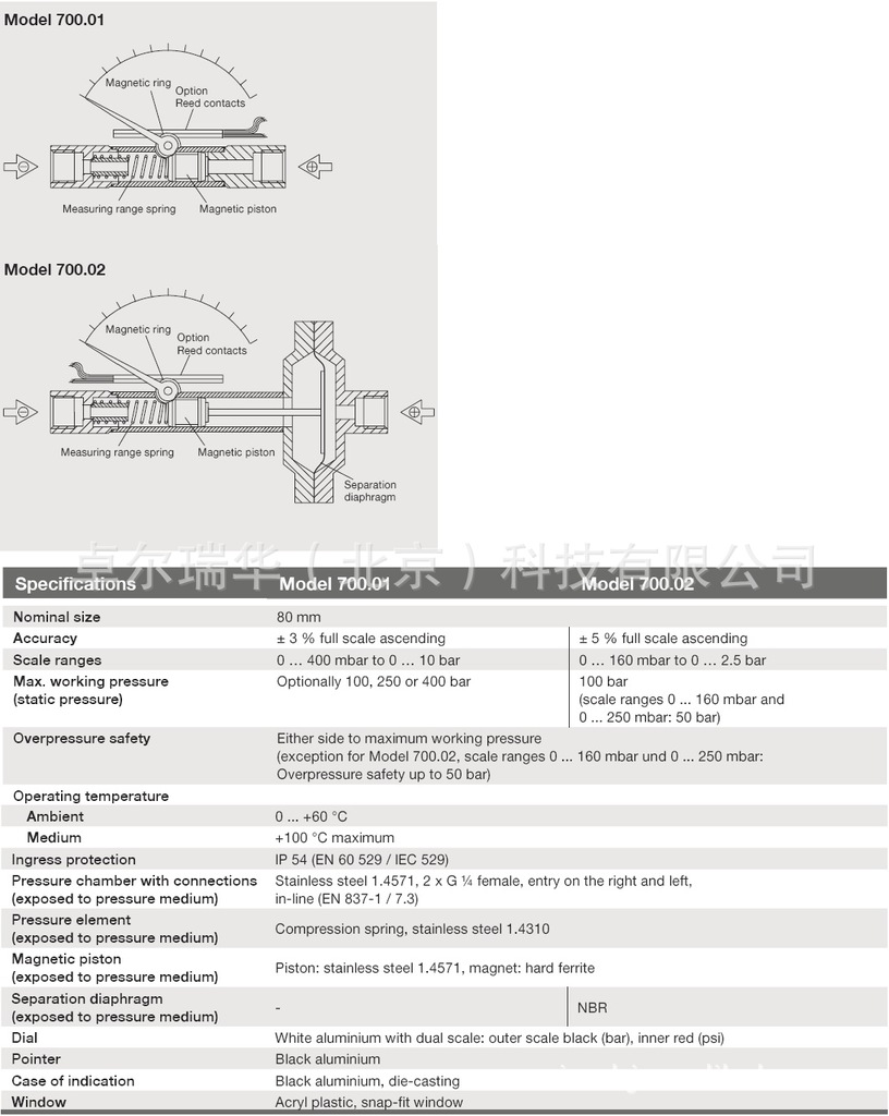
Design and operating
principle
Pressure p1 and p2 are given in the j and i
measuring medium chambers separated by magnetic piston under pressure or
magnetic piston and separation diaphragm for Model 700.02.
The difference
in pressure causes axial movement (measuring travel) of the piston supported by
a measuring range spring.
A magnetic ring mounted on the instrument
pointer follows the magnet‘s movement in the piston so that each piston position
is appropriated to a defined pointer position.
This design ensures
complete mechanical separation of the measuring system and the case and
eliminates external leakage.
The stream of volume from the measuring
chamber to the measuring chamber is minimised by the constructive design and
will not intefere with the process (only for Model 700.01).
For
applications where liquids or dirty and heavily contaminated media are to be
measured the version with a separation diaphragm Model 700.02, is suitable (no
volume flow from j and i media chamber).
Installation
Pressure entries identified j and i,j high pressure, i low pressure
Mounting by means of
rigid tailpipes,
panel mounting (optional
extra) or
device for surface mounting (optional extra)
?
Illustration of operating principle

Optional
extras
Other threaded pressure connection female or
male
Bottom or back pressure entry, connection left
Fine strainer
integrated in connection
Resettable max. drag
pointer
?
Following accessories may be retrofitted
locally:
Reed contacts, single or double change over contact, adjustable
from the outside
Panel mounting flange (only for Model 700.01)
Device for surface mounting
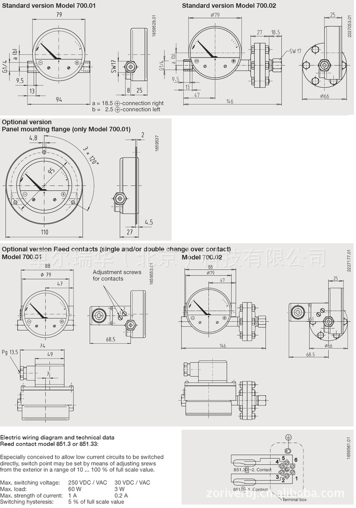
Dimensions in mm

Ordering information
Model /
Range / Scale / Process connection / Connector position / Overpressure safety
(working pressure max.) / Options?
欢迎致电咨询订购WIKA
700.01 700.02 差压表 带有磁铁活塞 可选项隔离膜 表径80mm
电话:010-51669912 56291930 15910733293
传真:010-51669912
QQ:823377546 1491421115 2636968574
邮箱:sales@zoriver.cn
公司官网:


