'
1. Product Dimensions &Outline Drawing & marking(Unit:mm)
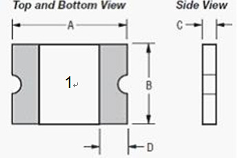
Model | A | B | C | D |
Min. | Max. | Min. | Max. | Min. | Max. | Min. |
PSMD100 | 2.00 | 2.30 | 1.20 | 1.50 | 0.75 | 1.25 | 0.20 |
2. Electrical Properties
Model | IH (A) | IT (A) | Vmax (v) | Imax (A) | T (Max time to trip) | Pdtyp (W) | Rmin (Ω) | R1max (Ω) |
(A) | (S) |
PSMD100 | 1.00 | 2.00 | 6.0 | 40 | 8.0 | 0.30 | 0.60 | 0.060 | 0.250 |
IH: Holding Current: maximum current at which the device will not trip in 25℃ still air.
IT: Tripping Current minimum current at which the device will trip in 25℃still air.
Vmax: Maximum voltage device can withstand without damage at rated current.
Imax: Maximum fault current device can withstand without damage at rated voltage.
Ttrip: Maximum time to trip(s) at assigned current.
Pdtyp: Rated working power.
Rmin: Minimum resistance of device prior to trip at 25℃.
Rmax: Maximum resistance of device prior to trip at 25℃.
R1max: Maximum resistance of device is measured one hours post reflow at 25℃.
Noted: All electrical funtion test is conducted after PCB mounted.
3. Thermal Derating Chart – Ihold(Amps)
Model | Ambient Operating Temperature |
-40℃ | -20℃ | 0℃ | 25℃ | 40℃ | 50℃ | 60℃ | 70℃ | 85℃ |
PSMD100 | 1.45 | 1.35 | 1.20 | 1.00 | 0.92 | 0.84 | 0.75 | 0.65 | 0.52 |
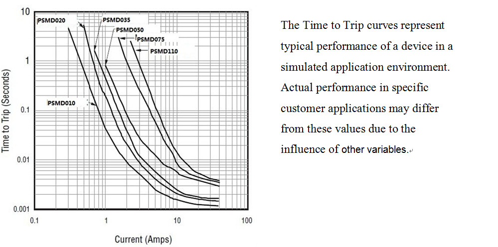
4. Typical time to trip at 25℃

'