'
1. Product Dimensions & Outline Drawing & marking(Unit:mm)
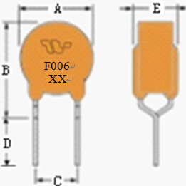
Model | A | B | C | D | E | Lead |
MAX | MAX | TYP | MIN | MAX | Φ |
TRF006 | 5.8 | 9.9 | 5.1 | 7.6 | 4.5 | 0.60 |
2.Electrical Properties
Model | IH (A) | IT (A) | Vmax OP Vdc | Imax (A) | Vmax Interrupt Vrms | Ttrip | Pdtyp (W) | Rmin (Ω) | Rmax (Ω) | R1max (Ω) |
(A) | (S) |
TRF006 | 0.060 | 0.120 | 60 | 3.0 | 250 | 0.50 | 2.0 | 1.0 | 22.0 | 36.0 | 56.0 |
IH: Holding Current: maximum current at which the device will not trip in 25℃ still air.
IT: Tripping Current minimum current at which the device will trip in 25℃still air.
Vmax: Maximum voltage device can withstand without damage at rated current.
Imax: Maximum fault current device can withstand without damage at rated voltage.
Ttrip: Maximum time to trip(s) at assigned current.
Pdtyp: Rated working power.
Rmin: Minimum resistance of device prior to trip at 25℃.
Rmax: Maximum resistance of device prior to trip at 25℃.
R1max:Maximum resistance of device measured one hour after tripping at 25℃.
3. Thermal Derating Chart – Ihold(Amps)
Model | Ambient Operating Temperature |
-40℃ | -20℃ | 0℃ | 25℃ | 40℃ | 50℃ | 60℃ | 70℃ | 85℃ |
TRF006 | 0.093 | 0.075 | 0.071 | 0.06 | 0.05 | 0.044 | 0.038 | 0.033 | 0.025 |
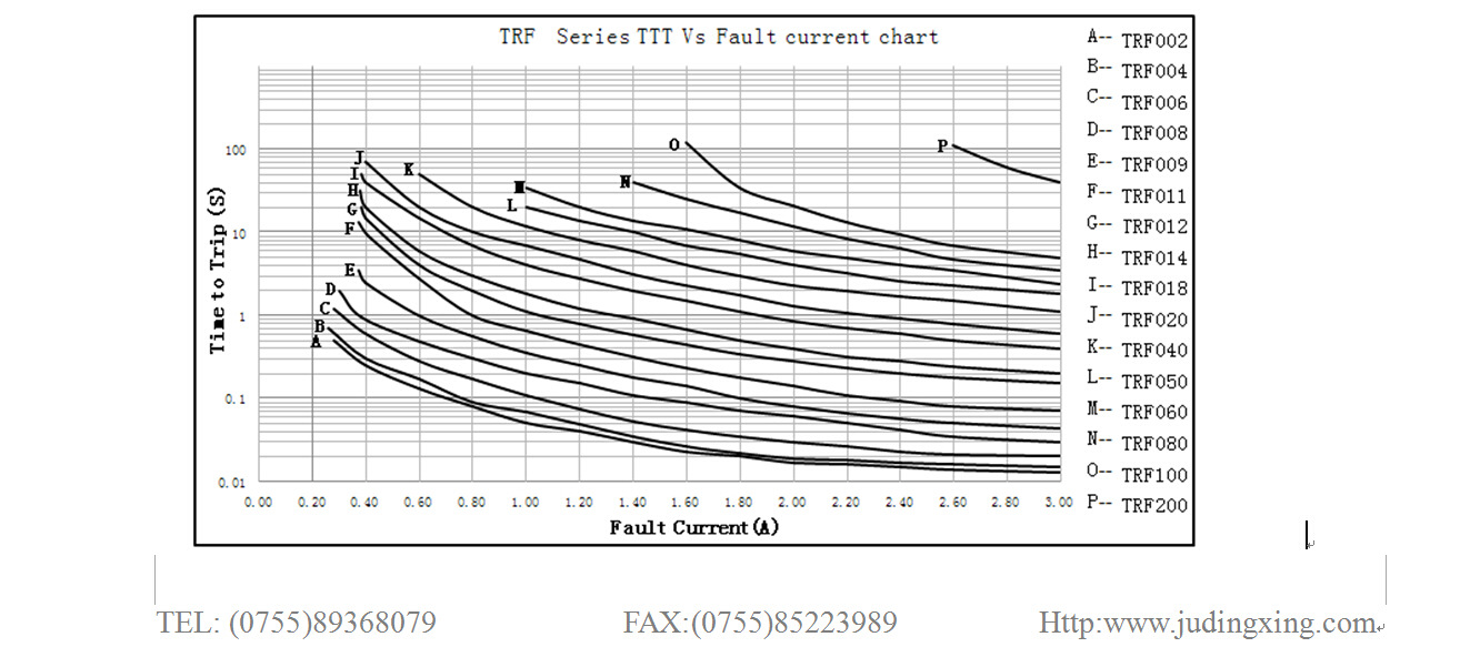
4. Typical time to trip at 25℃

'