联系人:魏工 电话:15882174684
座机:028-84472033
QQ:2030149354
产品资料:
The procedure to panel-mount the Controller Programmer is shown in Figure 2-3.
CAUTION: Do not remove the panel gasket, as this may result in
inadequate clamping of the instrument in the panel.
NOTE: When installing several Programmer Controllers side-by-side in
one cut-out, use the ratchets on the top/bottom faces.
Once the Controller is installed in its mounting panel, it may be subsequently
removed from its housing, if necessary, as described in Subsection 7.1.
2.3 CONNECTIONS AND WIRING
The rear terminal connections are illustrated in Figure 2-4.
WARNING ! This instrument is designed for installation in an
enclosure which provides adequate protection aganist electric
shock. All pertinent local regulations should be rigidly observed.
Consideration should be given to prevention of access to the
rear terminals by unauthorised personnel. Disregard for these
instructions may cause injury or death!
2.3.1 Mains (Line) Input
The Controller will operate on 96 - 264V AC 50/60Hz mains (line) supply. The power
consumption is approximately 4 VA. Power should be connected via a two-pole
isolating switch (preferably situated near the equipment) and a 1A fuse.
If the Controller has relay outputs in which the contacts are to carry mains (line)
voltage, it is recommended that the relay contact mains (line) supply should be
switched and fused in a similar manner but should be separate from the Controller
mains (line) supply.
2.3.2 24V (Nominal) AC/DC Supply
The supply connections for the 24V AC/DC option of the Controller are as shown in
Figure 2-4. Power should be connected via a two-pole isolating switch and a 315mA
slow-blow (anti-surge Type T) fuse.
With the 24V AC/DC supply option fitted, these terminals will accept the following
supply voltage ranges:
24V (nominal) AC 50/60Hz - 20 - 50V
24V (nominal) DC - 22 - 65V
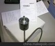
2.3.3 Thermocouple Input
The correct type of thermocouple extension leadwire or compensating cable must
be used for the entire distance between the Controller and the thermocouple,
ensuring that the correct polarity is observed throughout. Joints in the cable should
be avoided, if possible. The Controller’s CJC facility must be enabled (normal
conditions) for this input (see Subsection 6.4).
NOTE: Do not run thermocouple cables adjacent to power-carrying
conductors. If the wiring is run in a conduit, use a separate conduit for the
thermocouple wiring. If the thermocouple is grounded, this must be done at
one point only. If the thermocouple extension lead is shielded, the shield must
be grounded at one point only.
2.3.4 RTD Inputs
The compensating lead should be connected to Terminal 4. For two-wire RTD inputs,