联系人:张露云
联系电话:18958062346
LH8253MH253 Hall-effect sensor is a temperature stable, stress-resistant switch. Superior high-temperature performance is made possible through a dynamic offset cancellation that utilizes chopper-stabilization. This method reduces the offset voltage normally caused by device over molding, temperature dependencies, and thermal stress.
LH8MH includes the following on a single silicon chip: voltage regulator, Hall voltage generator, small-signal amplifier, chopper stabilization, Schmitt trigger, open-drain output. Advanced CMOS wafer fabrication processing is used to take advantage of low-voltage requirements, component matching, very low input-offset errors, and small component geometries.
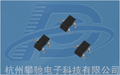
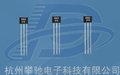
LHMH8 is rated for operation between the ambient temperatures –40℃ and +85℃ for the E temperature range. The four package styles available provide magnetically optimized solutions for most applications. Package types SO is an SOT-23(1.1 mm nominal height), SQ is an QFN2020-3(0.55 mm nominal height), a miniature low-profile surface-mount package, while package UA is a three-lead ultra mini SIP for through-hole mounting.
The package type is in aHalogen Free version was verified by third party Lab.
Features and Benefits
l CMOS Hall IC Technology
l Solid-State Reliability much better than reed switch
l Omni polar output switches with absolute value of North or South pole from magnet
l Low power consumption(2.6mA)
l High Sensitivity for reed switch replacement
l 100% tested at 125℃ for K.
l Small Size
l ESD HBM ±4KV Min
l COST competitive
Applications
l Solid state switch
l Lid close sensor for power supply devices
l Magnet proximity sensor for reed switch replacement in high duty cycle applications.
l Safety Key on sporting equipment
l Revolution counter
l Speed sensor
l Position Sensor
l Rotation Sensor
l Safety Key
091713Page 1Rev. 1.04
型号LH8253 | ||||||||||||||||||
| ||||||||||||||||||
Note:Exceeding the absolute maximum ratings may cause permanent damage. Exposure to absolute maximum- | ||||||||||||||||||
rated conditions for extended periods may affect device reliability. | ||||||||||||||||||
Electrical Specifications | ||||||||||||||||||
DC Operating Parameters TA=+25℃, VDD=5.0V | ||||||||||||||||||
Parameters | Test Conditions | Min | Typ | Max | Units | |||||||||||||
Supply Voltage,(VDD) | Operating | 2.5 | 6 | V | ||||||||||||||
Supply Current,(IDD) | Average | 2.6 | 6.0 | mA | ||||||||||||||
Output Low Voltage,(VDSON) | IOUT=10mA | 400 | mV | |||||||||||||||
Output Leakage Current,(Ioff) | IOFF | BOUT = 5V | 10 | uA | ||||||||||||||
Output Rise Time,(TR) | RL=10kΩ, CL =20pF | 0.45 | uS | |||||||||||||||
Output Fall Time,(TF) | RL=10kΩ; CL =20pF | 0.45 | uS | |||||||||||||||
Electro-Static Discharge | HBM | 4 | KV | |||||||||||||||
Operate Point, | (BOPS) | S pole to branded side, B > BOP, Vout On | 30 | 60 | Gauss | |||||||||||||
(BOPN) | ||||||||||||||||||
N pole to branded side, B > BOP, Vout On | -60 | -30 | ||||||||||||||||
Release Point | (BRPS) | S pole to branded side, B < BRP, Vout Off | 5 | 25 | Gauss | |||||||||||||
(BRPN) | ||||||||||||||||||
N pole to branded side, B < BRP, Vout Off | -25 | -5 | ||||||||||||||||
Hysteresis,(BHYS) | |BOPx - BRPx| | 5 | Gauss | |||||||||||||||