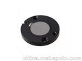
Cyoptics(先后被Avago和Broadcom收购) E2560系列TOSA, 超小紧凑尺寸, 内部集成DFB激光器, EA电吸收调制器,以及背向PD和TEC. 可以实现高达10Gbps速率的光信号传输, 高集成度可以有效降低产品的尺寸和成本, 非常适合C波段范围内2km短距离或40km色散补偿通信. 注: E2560S34工作波长1550.12nm
10Gbps Transmitter, CyOptics E2560S34, Electro-absorption Modulated Laser, Integrated EML Module
Description
The E2560-series EML is designed for 10 Gb/s DWDM or TDM transmission applications. The EML integrates a CW laser with an electro-absorptive modulator in the same semiconductor chip and are an extension of CyOptics’ existing E2500-series of devices. These devices can replace external modulators that are often bulkier, more expensive, and require more drive electronics than the EML. The E2560 series use a small-profile GPO ™ (SMP) connector to handle the RF signal. The package also contains a thermoelectric cooler, thermistor, rear-facet monitor photodiode, and an optical isolator.
The nominal input impedance of the E2560 version is 50Ohms. The package is qualified to the Telcordia Technologies™ TA-TSY-000468 standard.
E2560 is available in a range of ITU-T C-band wavelengths for use in DWDM systems operating at 10 Gb/s per channel. Also, E2560-series is offered as a single-channel device operating within a wavelength range of 1530 nm—1563 nm (Note: E2560S34 is at wavelength of 1550.12nm)
The devices exhibit excellent wavelength stability, supporting operation at 100 GHz channel spacing over 20 years (assuming an end-of-life aging condition of <100 pm). Typically, no external wavelength stabilization is required in systems of this type, using the CyOptics E2560 EMLs. The package also offers excellent stability of wavelength vs. case temperature, with a maximum coefficient of ±0.5 pm/C.
Module Characteristics
Features
- Integrated electro-absorptive modulator
- 1.5um wavelength
- High Output Power
- Specified for
9.95 Gb/s operation - For use up to 40 km (800ps/nm)
- Low modulation voltage
- Temperature stabilized
- Wavelength selectable to ITU-T standards
- Ultra-stable wavelength aging for DWDM
Applications
- SONET/SDH applications
- Ultrahigh capacity WDM system application
- High-speed data communication
- Digitized video
Module Characteristics
Table
1. Module Characteristics
| Parameter | Description |
| Package Type | 7-pin package with GPOTM-type connector RF input. |
| Fiber | Standard single-mode fiber. |
| Optical Connector | Various connectors available on request. |
| RF Input (SMP-type connector) | Impedance 50 W |
| Bit Rate | up to10 Gb/s. |
Pin Information
Table
2. Pin Descriptions
| Pin Number | Pin Name | Description |
| 1 | THERM | Thermistor |
| 2 | THERM | Thermistor |
| 3 | LASER+ | Laser anode* |
| 4 | BACK DET– | Monitor anode (–) |
| 5 | BACK DET+ | Monitor cathode (+) |
| 6 | TEC+ | Thermoelectric cooler (+) |
| 7 | TEC– | Thermoelectric cooler (–) |
* Laser cathode and modulator ground are connected to case.
Target Specifications
Absolute Maximum Ratings
Stresses in excess of the absolute maximum ratings can cause permanent damage to the device. These are absolute stress ratings only. Functional operation of the device is not implied at these or any other conditions in excess of those given in the operational sections of the data sheet. Exposure to absolute maximum ratings for extended periods can adversely affect device reliability.
Table
3. Absolute Maximum Ratings
| Parameter | Conditions | Min | Max | Unit |
| Laser Diode Reverse Voltage | CW | — | 2 | V |
| Laser Diode Forward Current | CW | — | 150 | mA |
| Optical Output Power | CW | — | 10 | mW |
| Modulator Reverse Voltage | — | — | 5 | V |
| Modulator Forward Voltage | — | — | 1 | V |
| Monitor Diode Reverse Voltage | — | — | 10 | V |
| Monitor Diode Forward Voltage | — | — | 1 | V |
| Storage Temperature | — | — | –40 to +85 | C |
| Operating Temperature | — | — | –10 to +75 | C |
| Thermistor Temperature** | — | — | 100 | C |
| Thermoelectric Cooler in Heating Mode** | — | — | 0.5 | A |
Minimum and maximum values specified over operating case temperature range. Typical values are measured at room temperature (25C) unless otherwise noted.
Table
4. Optical and Electrical Specifications (Chip operating temp. = 20C to 35C, except where noted.)
| Parameter | Symbol | Conditions | Min | Max | Unit |
| Threshold Current (BOL) | ITH | — | 5 | 35 | mA |
| Forward Voltage | VF | IF = IOP @ TOP | — | 2.2 | V |
| Operating Current | IOP | — | 50 | 100 | mA |
| Threshold Power | PTH | IF = ITH, VM *= 0V | — | 80 | mW |
| Fiber Output Power (Average) , BOL | PAVG | Note 1 | 0.5 | +3.0 | dBm |
| Fiber Output Power (Average) , EOL | PAVG | 0 | 2.5 | dBm | |
| Peak Wavelength | lPK | Note 1 | 1528 | 1564 | nm |
| (Wavelength can be specified to the ITU | |||||
| wavelength channels. See Table 5.) | |||||
| Side-mode Suppression Ratio | SMSR | VM = 0 ,IF = IOP, TOP | 30 | — | dB |
| Peak to Peak Modulator Voltage | VPP | 1.5 | 2.5 | V | |
| On-State Modulator Voltage | VON | -1.0 | 0 | V | |
| Dispersion Penalty, BER = 10–12 D = 800 ps/nm | DP | Notes 1,2 | — | 2.0 | dB |
| Modulator | |||||
| RF Extinction Ratio | ERRF | Notes 1,4 | 10 | — | dB |
| RF Return Loss (0 GHz to 8 GHz) | S11 | VM = –0.8V, IF = IOP | 10 | — | dB |
| RF Return Loss (8 GHz to 10 GHz) | S11 | VM = –0.8V, IF = IOP | 8.5 | — | dB |
| –3 dB Bandwidth | BW | VM = –0.8V,IF = IOP | 11 | — | GHz |
| Rise/Fall Time (20%—80%) | tR/tF | Note 4 | — | 40 | ps |
| Monitor Diode | |||||
| Monitor Current | IBD | VBD = 5V, IF = IOP | 40 | 1100 | mA |
| Dark Current | ID | VBD = 5 V | — | 0.1 | mA |
| Capacitance | C | VBD = 5V, F = 1 MHz | — | 25 | pF |
| Thermistor | |||||
| Resistance | RTHERM | T = 25C | 9.5 | 10.5 | kW |
| Thermistor Current | ITC | — | 10 | 100 | mA |
| Thermistor B Constant | B | — | 3700 | 4100 | — |
| Thermoelectric Cooler (TEC) | |||||
| TEC Cooling Current** | ITEC | Note 3 | — | 1.3 | A |
| TEC Voltage | VTEC | — | 2.6 | V | |
| TEC Power | PTEC | — | 3.4 | W | |
| TEC Cooling Capacity | DT | — | 55 | C | |
| Optical Isolation | |||||
| Optical Isolation | — | 30 | — | dB |
| Parameter | Symbol | Conditions | Min | Max | Unit |
| Package | |||||
| Wavelength vs. Case Temp. | dl/ dT | TCASE = –10 C to +75 C | –0.5 | 0.5 | pm/C |
| Output Power Stability | Tc= -10C/25C/75C | 1.0 | dB |
* VM= Modulator Voltage (DC)**Maximum TEC current for Heating is less than 0.5A
- Modulated for 40 km (800ps/nm) operation. Modulated operational values are defined to be I = IOP, T = TOP, at all specified operating conditions,
9.95 Gb/s modulation, 231– 1 PRBS (operating parameters: Iop, Top, Von for 40 km will be provided). Laser diode temperature can be set in a 20 C to 35 C range to take advantage of wavelength tuning, provided that it will meet all other specs at this preset temperature. - Over 800ps/nm (80 km).
- TCASE = 75 C, Top(LASERCHIP) = 20C to 35
- Without filter, O/E bandwidth>20GHz.
Ordering Information
Table
5. Ordering Information:
| ITU-T Wavelength (nm) | Frequency | Code1 |
| 1550.12 | 193.4 | E2560S34 |
| 1529.55 | 196.0 | E2560S60 |
- Other connectors are available on request.
Table
6. Ordering Information: (Connector Type)
| Device Code1 | Connector Type2 |
| E2560Sxx | LC |
- The xx notation in the device code refers to the ITU channel designation ( for details see Table 5 ).
- Other connectors available on request
GPO is a trademark of Gilbert Engineering.Telcordia Technologies is a trademark of Telcordia Technologies, Inc.IEC is a registered trademark of The International Electrotechnical Commission.