热销WOMA沃玛552 P24高压泵(原厂报价)货期短

泉州市双环贸易发展有限公司
中国 泉州
产品属性
图文详情
品牌推荐
品牌
WOMA沃玛
型号
552 P24
作用原理
管道泵
输送介质
水泵
用途
增压泵
驱动方式
电动泵
介质温度类型
高温泵
材质
金属
最大出口压力类型
超高压泵pd≥100MPaMPa
最大出口压力数值
行业标准MPa
额定流量Q
行业标准m3/h
额定扬程H
行业标准m
叶片式泵叶轮级数
多级泵
叶片式泵吸入方式
双吸泵
叶片式泵叶轮形式
敞开式叶轮
叶片式泵壳体型式
节段式
叶片式泵泵轴位置
卧式泵
额定转速n
行业标准r/min
轴功率Pa
行业标准kW
泵效率η
行业标准%
容积效率ηv
行业标准%
汽蚀余量NPSH
行业标准m
允许吸上高度
行业标准m
吸入口直径Ds
行业标准mm
排出口直径Dd
行业标准mm
活塞/柱塞直径
行业标准mm
活塞/柱塞行程
行业标准mm
往复次数n
行业标准r/min
计量精度
行业标准
最大允许颗粒直径
行业标准mm
介质粘度ν
行业标准mm2/s
介质温度
行业标准℃
工作温度
行业标准℃
环境温度
行业标准℃
外形尺寸
行业标准mm
重量
行业标准kg
行业标准
1
行业标准
1
行业标准
1
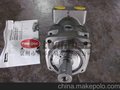
 德国WOMA沃玛552 P24
高压清洗泵 德国原装进口,出厂价销售,货期短,质量100%保证,欢迎比价。
- The WOMANozzle Flow-Chart
- The WOMA Nozzle Flow-Chart
- enables the estimation of
- a nozzle index depending on
- water volume flow rate and
- operating pressure. If, in turn,
- the nozzle index is given, the
- permissible values for operating
- pressure and volume flow rate
- can be estimated.
- Attention:
- The chart is valid only for
- operating pressures up to
- 1,500 bar (22,000 psi) !
- Calculation software
- WOMA offers computer
- assisted calculation programmes
- for estimating volume flow
- rate, nozzle diameter, operat-
- ing pressure, and hydraulic
- power. The diagramme
- shows just some examples
- of calculated relations.
- Volume flow rate in l/min
- 1 l/min = 0.264 US gal/min = 0.22 Imp. gal/min)
- Nozzle diameter in mm
- (1 mm = 0.004 in)
- 0.2 0.3 0.4 0.5 0.6 0.7 0.8 0.9 1
- 30
- 25
- 20
- 15
- 10
- 5
- 0
- 2,000 bar, continuous flow channel
- 2,500 bar, continuous flow channel
- 2,500 bar,
- sapphire insert
- 2,000 bar, sapphire insert
- Relative pressure loss in bar/m (1 bar/m = 4.42 psi/in)
- DN 4 DN 5
- Volume flow rate in l/min (1 l/min = 0.264 US gal/min = 0.22 Imp. gal/min)
- 10 20 30 40 50 100 200 300 400500 1,000
- 10,000
- 1,000
- 100
- 10
- 1
- 0.1
- 0.01
- DN 6
- DN 8
- DN 10
- DN 12
- DN 20
- DN 25
- DN 32
- Nominal hose width in mm (1 mm = 0.04 in)
- © WOMA Apparatebau GmbH PR-ZU – 12/05-E · Subject to technical modification
- High-Pressure Hoses
- Estimation of pressure losses in high-pressure hoses
- The WOMA Pressure Loss-Chart enables the estimation of relative pressure
- losses in hoses depending on water volume flow rate and nominal hose width.
- Attention: Pressure losses in armatures are not considered!
- WOMA’s high-pressure hose programme contains hoses
- with the following technical parameters:
- Nominal Maximum oper- Maximum Specific Bend
- width ating pressure delivery length weight radius
- in mm in bar in m in kg/m in mm
- DN 4 1,000/2,800 200 0.10/0.29 75/140
- DN 5 1,000/1,400 200 0.20/0.25 95/120
- 2,500/4,000 200 0.41/0.54 150/200
- DN 6 1,000 200 0.25 110
- DN 8 750/1,000 200 0.22/0.40 120/175
- 1,400/ 2,100 200 0.40/0.60 175/200
- 2,500 200 0.75 200
- DN 10 1,250/2,000 100/200 0.87/1.01 180/250
- DN 12 1,100/1,400 100/200 1.22/1.36 200/300
- DN 20 1,000/1,400 100/200 2.10/1.82 280/350
- DN 25 700 100 2.08 350
- DN 32 560 100 2.59 460
- Application of the
- WOMA Pressure Loss-Chart:
- Example: Volume flow rate: 100 l/min,
- Nominal width: 12 mm,
- Hose length: 40 m,
- Complete pressure loss ?
- Solution: Mark the volume flow rate value
- at the horizontal axis ? go upward up to the
- inclined DN 12-line ? from the intersection
- point go to the left meeting the pressure
- loss-axis ? read value: 1.3 bar/m ? complete
- pressure loss: 1.3 bar/m ? 40 m = 52 bar
- (755 psi)
- 1 mm = 0.04 in 1 bar = 14.5 psi 1 m = 3.28 ft 1 kg = 2.205 lb
- WOMA Apparatebau GmbH
- Werthauser Str. 77–79 · D-47226 Duisburg
- P.O. Box 141820 · D-47208 Duisburg
- Phone +49 2065 304-0 · Fax +49 2065 304-200
- Internet: www.woma.de
- Delivery Programme
- High-pressure plunger pumps
- High-pressure water jet systems
- High-pressure water tools
- and accessories
- Fields of Application
- Agriculture
- Automotive and aviation industry
- Beverage industry
- Cement industry
- Chemical industry
- Construction and concrete industry
- Engineering industry
- Food industry
- Glass, porcelaine, ceramic industry
- Iron, steel and metal industry
- Mining
- Municipal services
- Offshore industry
- Power industry
- Public transport
- Pulp and paper industry
- Ship building
- Wood working industry
- High-Pressure Plunger Pumps
- 02-Line (up to 750 bar)
- 252
- 552
- 1002
- 1502
- 2502
- Technical Data
- High-Pressure Plunger Pump Type 252 / 552
- All dimensions in mm
- Thread “M“ as per DIN 13/ISO 261
- Thread “G“ as per DIN ISO 228/1
- Technical Data:
- ? Oil capacity: approx. 1.8 l
- ? Weight: approx. 50 kg net
- ? Stroke: 45 mm/1.77 inch
- ? Inlet pressure required*: 2 bar/30 psi
- ? Rod force: 7.5 kN
- * Depends on operating mode, crank shaft speed and water temperature
- Suction on
- both sides
- G 1 1/2
- Discharge on
- both sides
- G 3/4
- M16-35 deep
- Discharge on
- both sides
- G 3/4
- Key per
- DIN 6885 Page 1
- 475
- 365
- 300
- 90
- 90
- 160 15 18
- 40
- 30
- 36
- 210
- 100 35
- 220
- 260
- 272
- 310
- 136 220
- 80
- ø30 n6
- Performance Chart Pump Type 252
- Plungerdiameter Crank shaft Required drive Nominal flow rate Maximum permissible
- (mm) (Rpm) (kW) USG pm IMPG pm (l/min) operating pressure (psi/bar)
- P 22
- 1,000 18 13.5 11.2 51
- 2,900/200
- 750 13 10.0 8.4 38
- P 24
- 1,000 18 16.1 13.4 61
- 2,320/160
- 750 14 11.9 9.9 45
- P 26
- 1,000 18 18.8 15.6 71
- 1,958/135
- 750 13 14.0 11.7 53
- P 30
- 1,000 18 25.1 20.9 95
- 1,450/100
- 750 13 18.8 15.6 71
- P 35
- 1,000 18 34.1 28.4 129
- 1,088/ 75
- 750 14 25.6 21.3 97
- Key per DIN 6885
- Page 1
- Suction G 1 1/2
- Discharge
- M 30 x 1.5
- Key per DIN 6885
- Page 1
- 290
- 630
- 145
- 330
- 150 150
- ø35 k6
- ø40 k6
- 340
- 330
- 245 90
- 408
- 140
- 295
- 93
- 30
- 60
- 30
- ø19
- 31
- 72
- 216
- 236 284
- 108 60
- All dimensions in mm
- Thread “M“ as per DIN 13/ISO 261
- Thread “G“ as per DIN ISO 228/1
- Performance Chart Pump Type 552
- Plungerdiameter Crank shaft Required drive Nominal flow rate Maximum permissible
- (mm) (Rpm) (kW) USG pm IMPG pm (l/min) operating pressure (psi/bar)
- P20
- 1000 47 10.30 8.58 39
- 9,425/650
- 750 35 7.66 6.38 29
- P24
- 1000 48 15.32 12.76 58
- 6,500/450
- 750 37 11.36 9.46 43
- P26
- 1000 50 17.96 14.96 68
- 5,800/400
- 750 37 13.47 11.22 51
- P30
- 1000 50 24.04 20.02 91
- 4,400/300
- 750 37 17.96 14.96 68
- P35
- 1000 51 33.02 27.50 125
- 3,200/220
- 750 38 24.83 20.68 94
- P40
- 1000 51 43.59 36.30 165
- 2,500/170
- 750 38 32.49 27.06 123
- P45
- 1000 52 55.21 45.97 209
- 1,958/135
- 750 38 41.48 34.54 157
- Technical Data:
- ? Oil capacity: approx. 4.5 l
- ? Weight: approx. 160 kg net
- ? Stroke: 44.5 mm/1.75 inch
- ? Inlet pressure required*: 2 bar/3 bar – 30 psi/43,5 psi (1000 Rpm)
- ? Rod force: 21 kN
- * Depends on operating mode, crank shaft speed and water temperature
- High-Pressure Plunger Pump Type 1002
- All dimensions in mm
- Thread “M“ as per DIN 13/ISO 261
- Thread “G“ as per DIN ISO 228/1
- Technical Data:
- ? Oil capacity: approx. 6 l
- ? Weight: approx. 254 kg net
- ? Stroke: 73 mm/2.88 inch
- ? Inlet pressure required: 2 bar/30 psi
- ? Rod force: 29.4 kN
- 315
- 864
- 484 295
- 82 82
- suctionG1 1/2
- 299
- 230,5
- 330
- 81,5
- key per DIN 6885 Bl.1
- 301
- 167 134
- 41 ø 40 k6
- ø 19
- discharge M30x1,5
- 50 45
- 175 170
- 40
- 345
- key per DIN 6885 Bl.1
- ø 35 k6
- 284 226
- 365 98
- 295
- 435
- 455
- suction G1 1/2
- 239
- 239
- 40,5
- ? Installation variations
- Performance Chart Pump Type 1002
- Plunger-
- Gear Ratio
- Crank Required
- Nominal flow rate
- Maximum permissible
- diameter Pinion shaft (Rpm) shaft drive USG IMPG operating pressure
- (mm) 1,500 1,800 (Rpm) (kW) pm pm (l/min) (psi/bar)
- 3.63 495 56 10.6 8.8 40
- P 22 3.00 500 56 10.6 8.8 40 10,875/750
- 3.63 413 46 8.7 7.3 33
- 3.63 495 56 14.5 12.1 55
- P 26 3.00 500 57 14.8 12.3 56 7,975/550
- 3.63 413 47 12.2 10.1 46
- 3.63 495 58 27.5 22.9 104
- P 35 3.00 500 58 27.7 23.1 105 4,350/300
- 3.63 413 48 22.7 18.9 86
- 3.63 495 58 35.9 29.9 136
- P 40 3.00 500 58 36.2 30.1 137 3,335/230
- 3.63 413 48 29.9 24.9 113
- 3.63 495 57 45.4 37.8 172
- P 45 3.00 500 58 46.0 38.3 174 2,610/180
- 3.63 413 48 37.8 31.5 143
- High-Pressure Plunger Pump Type 1502
- 133
- 41
- 211
- 346 41
- 90
- Suction
- IG 1 1/2
- 240
- 630
- 675
- 975
- Mounting space
- 250
- Oil sight glass
- Connection for Oil cooling G 1/2
- 83
- Ø19
- 445
- 185
- Mounting space
- 495
- Ø50 k6
- 200
- Discharge
- 180 75
- 45
- 100
- Key 14x72 per
- DIN 6885 Page 1
- 475
- Mounting space
- 200
- 255
- 351
- 445
- 268 304
- 572
- Suction
- IG 1 1/2
- All dimensions in mm
- Thread “M“ as per DIN 13/ISO 261
- Thread “G“ as per DIN ISO 228/1
- Technical Data:
- ? Oil capacity: approx. 9 l
- ? Weight: approx. 319 kg net
- ? Stroke: 95 mm/3.74 inch
- ? Inlet pressure required*: from P 40:
- 2 – 5 bar/30 – 75 psi
- ? Rod force: 40 kN
- * Depends on plunger diameter
- Performance Chart Pump Type 1502
- Plunger-
- Gear Ratio
- Crank Required
- Nominal flow rate
- Maximum permissible
- diameter Pinion shaft (Rpm) shaft drive USG IMPG operating pressure
- (mm) 1,500 1,800 2,100 (Rpm) (kW) pm pm (l/min) (psi/bar)
- 4.57 459 91 17.7 14.7 67
- 3.69 488 98 19.0 15.8 72
- P 26 4.57 393 79 15.3 12.8 58
- 10,875/750
- 2.96 507 101 19.5 16.3 74
- 3.69 407 82 15.9 13.2 60
- 4.57 328 66 12.7 10.6 48
- 4.57 459 93 23.8 19.8 90
- 3.69 488 99 25.4 21.1 96
- P 30 4.57 393 79 20.3 16.9 77
- 8,193/565
- 2.96 507 102 26.2 21.8 99
- 3.69 407 82 21.1 17.6 80
- 4.57 328 66 16.9 14.1 64
- 4.57 459 94 33.0 27.5 125
- 3.69 488 100 35.1 29.3 133
- P 35 4.57 393 81 28.3 23.5 107
- 6,018/415
- 2.96 507 104 36.5 30.4 138
- 3.69 407 84 29.3 24.4 111
- 4.57 328 67 23.5 19.6 89
- 4.57 459 96 43.3 36.1 164
- 3.69 488 101 46.0 38.3 174
- P 40 4.57 393 82 37.0 30.8 140
- 4,640/320
- 2.96 507 105 47.8 39.8 181
- 3.69 407 85 38.3 31.9 145
- 4.57 328 68 30.9 25.7 117
- 4.57 459 94 54.7 45.5 207
- 3.69 488 101 58.4 48.6 221
- P 45 4.57 393 81 47.0 39.2 178
- 3,625/250
- 2.96 507 104 60.5 50.4 229
- 3.69 407 84 48.6 40.5 184
- 4.57 328 68 39.1 32.6 148
- ? Installation variations
- High-Pressure Plunger Pump Type 2502
- All dimensions in mm
- Thread “M” as per DIN 13/ISO 261
- Thread “G” as per DIN ISO 228/1
- Technical Data:
- ? Oil capacity: approx. 8 l
- ? Weight: approx. 350 kg net
- ? Stroke: 95 mm/3.74
- ? Inlet pressure required*: from P 40: 2 bar/30 psi
- ? Rod force: 70 kN
- * Depends on operating mode, crank shaft speed and water temperature
- Performance Chart Pump Type 2502
- Plunger-
- Gear ratio
- Crank Required
- Nominal flow rate
- Maximum permissible
- diameter Pinion shaft (Rpm) shaft drive USG IMPG operating pressure
- (mm) 1,500 1,800 2,100 (Rpm) (kW) pm pm (l/min) (psi/bar)
- 4.52 464 120 24.0 20.0 91
- 3.57 504 130 26.2 21.8 99
- P 30
- 4.52 398 103 20.6 17.2 78
- 10,875/750
- 3.04 493 127 25.4 21.1 96
- 3.57 420 108 21.7 18.0 82
- 4.52 331 85 17.2 14.3 65
- 4.52 464 143 32.8 27.3 124
- 3.57 504 155 35.4 29.5 134
- P 35
- 4.52 398 122 28.0 23.3 106
- 9,425/650
- 3.04 493 152 34.9 29.0 132
- 3.57 420 129 29.6 24.6 112
- 4.52 331 102 23.2 19.4 88
- 4.52 464 146 43.9 36.5 166
- 3.57 504 158 47.6 39.6 180
- P 40
- 4.52 398 125 37.5 31.2 142
- 7,250/500
- 3.04 493 155 46.5 38.7 176
- 3.57 420 132 39.6 33.0 150
- 4.52 331 104 31.2 26.0 118
- 4.52 464 149 55.5 46.2 210
- 3.57 504 162 60.2 50.2 228
- P 45
- 4.52 398 128 47.6 39.6 180
- 5,800/400
- 3.04 493 159 58.9 49.1 223
- 3.57 420 135 50.2 41.8 190
- 4.52 331 106 39.6 33.0 150
- Discharge
- Suction IG 1 1/2
- Mounting space
- Connection for
- Oil cooling G 1/2
- Key 14x72
- per DIN 6885 Page 1
- Oil sight glass
- Suction IG 1 1/2
- 255
- 445
- 133
- 475
- 495
- 445
- 346
- 100
- 83
- 41 41
- 211
- 318 304
- 622
- 180
- Ø 19
- 180 185 45
- 75
- 575
- 919
- 621
- 90
- 240
- 358
- Ø50 k6
- Technical Data
- ? Installation variations
- Technical Advantages
- Pump Gear
- ? Proven pump gear with forced oil
- lubrication and variable gear ratios
- Pump Head
- ? Easy-to-service pump head in block
- design made of treated forged steel
- ? Flange-mounted suction and
- discharge channel
- ? Valve design for high efficiency and
- easy servicing
- ? Maintenance-free plunger seal with
- lamellar packing
- ? Plungers made of ceramics


- (Types 252 to 2502)
- ? Long service live
- Additional Equipment
- ? Pressure regulating valve with
- pneumatic control
- ? Pneumatically controlled
- 2/2-way pressure relief valve
- ? Pneumatically controlled
- 3/2-way valve
- ? Pneumatically controlled
- high-pressure valves for parallel
- operation of several users
- Options
- ? Pump head, cylinders and valves
- made from special materials for
- aggressive media, e.g. seawater
- High-pressure
- waterjet system
- with electrically
- driven high-
- pressure plunger
- pump Type 752
- High-pressure
- cleaning system
- in explosion
- proofness design
- with electric drive
- and high-pressure
- plunger pump
- Type 1502
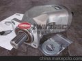
- High-pressure cleaning
- system with electric
- motor and high-pressure
- plunger pump Type 552
- WOMA Apparatebau GmbH
- Werthauser Str. 77–79 · D-47226 Duisburg
- P.O. Box 141820 · D-47208 Duisburg
- Phone +49 2065 304-0 · Fax +49 2065 304-200
- Internet: www.woma.de
- E-mail: info@woma.de
- HP-P-02-Line– 12/05-E · Subject to technical modification
- Delivery Programme
- High-pressure plunger pumps
- High-pressure water jet systems
- High-pressure water tools
- and accessories
- Fields of Application
- Agriculture
- Automotive and aviation industry
- Beverage industry
- Cement industry
- Chemical industry
- Construction and concrete industry
- Engineering industry
- Food industry
- Glass, porcelaine, ceramic industry
- Iron, steel and metal industry
- Mining
- Municipal services
- Offshore industry
- Power industry
- Public transport
- Pulp and paper industry
- Ship building
- Wood working industry
- High-Pressure Plunger Pumps
- 03-Line (up to 250 bar)
- 1003
- 1503
- 2503
- Technical Data
- High-Pressure Plunger Pump Type 1003 / 1503
- All dimensions in mm
- Thread ”M“ as per DIN 13/ISO 261
- Thread ”G“ as per DIN ISO 228/1
- * For plunger diameters
- P 50 and P 55 this
- dimension is 20 mm longer
- Performance Chart Pump Type 1503
- Plunger
- Gear ratio
- Crank Required Nominal flow rate Max. permissible
- diameter Pinion shaft (Rpm) shaft drive USG IMPG operating pressure
- (mm) 1,500 1,800 (Rpm) (kW) pm pm l/min (psi/bar)
- 3.69 488 99 70.53 58.73 267
- P 50 2.96 507 102 73.44 61.15 278 2,900/200
- 3.69 406 82 58.91 49.05 223
- 3.69 488 102 85.86 71.49 325
- P 55 2.96 507 106 89.03 74.13 337 2,500/170
- 3.69 406 85 71.33 59.39 270
- 3.69 488 100 102.23 85.13 387
- P 60 2.96 507 104 106.20 88.43 402 2,000/140
- 3.69 406 83 85.33 71.05 323
- Technical Data:
- ? Oil capacity: approx. 10 l
- ? Weight: approx. 285 kg net
- ? Stroke: 95 mm/3.74 inch
- ? Rod force: 40 kN
- 211 133 650
- 41
- 83
- 41
- 22
- 228
- 162
- 250
- 75
- 346
- Mounting space
- Discharge
- G 1 1/4
- Suction
- IG 3
- 689 (P60: 669)
- 994 (P60: 974)
- Oil sight
- glass
- Connection for
- Oil cooling G1/2
- 445
- 572
- 268 304
- 331
- 322
- 255
- 495
- 445
- 475
- 100
- 370
- Mounting space
- ø19
- 200
- ø50k6
- Key 14x72
- per DIN 6885 Page 1
- All dimensions in mm
- Thread “M“ as per DIN 13/ISO 261
- Thread “G“ as per DIN ISO 228/1
- Technical Data:
- ? Oil capacity: approx. 6 l
- ? Weight: approx. 219 kg net
- ? Stroke: 95 mm/3.74 inch
- ? Rod force: 29.7 kN
- Performance Chart Pump Type 1003
- Plunger-
- Gear Ratio
- Crank Required
- Nominal flow rate
- Maximum permissible
- diameter Pinion shaft (Rpm) shaft drive USG IMPG operating pressure
- (mm) 1,500 1,800 (Rpm) (kW) pm pm (l/min) (psi/bar)
- 3.63 495 58 55.5 46.2 210
- P 50 3.00 500 59 56.0 46.6 212 2,175/150
- 3.63 413 49 46.2 38.5 175
- Discharge G1 1/4
- Suction G3
- Connection for oil cooling G1
- Oil sight glass
- 882
- 295 520
- 495
- 82
- 248
- 216
- 63
- 10
- 150
- 299
- 315
- 82
- 239
- Mounting space
- 435
- 455
- 580
- 239
- 250
- 301
- 167
- 98 365
- 284 226
- 180
- Mounting space
- 134
- 41 Key 12x70
- per DIN 6885 Page 1
- 200
- ø 19
- 405
- 336
- Mounting space
- 40
- ø 40 k6
- ø 35 k6
- Key 10x20
- per DIN 6885 Page 1
- ? Installation variations
- ? Installation variations
- High-Pressure Plunger Pump Type 2503
- 633 (P60: 613)
- 935 (P60: 915)
- 41
- 133
- 83
- Discharge G1 1/4
- Suction IG 3
- 22
- Connection for
- Oil cooling G 1/2
- Oil sight glass
- 4 1
- 211
- 75
- 66
- 162
- Mounting space
- 495
- 180
- ø50 k6
- Key 14x72
- per DIN 6885 Bl1
- ø19
- 200
- Mounting space
- 445
- 100
- 370
- 445
- 304
- 622
- 322
- 318
- All dimensions in mm
- Thread ”M“ as per DIN 13/ISO 261
- Thread ”G“ as per DIN ISO 228/1
- Performance Chart Pump Type 2503
- Plunger
- Gear ratio
- Crank Required Nominal flow rate Max. permissible
- diameter Pinion shaft (Rpm) shaft drive USG IMPG operating pressure
- (mm) 1,500 1,800 2,100 (Rpm) (kW) pm pm l/min (psi/bar)
- 4.52 464 118 68.4 57.0 259
- 3.57 504 128 74.2 61.8 281
- P50
- 4.52 398 101 58.6 48.8 222
- 3,625/250
- 3.04 493 125 72.6 60.5 275
- 3.57 420 106 61.8 51.5 234
- 4.52 331 84 48.9 40.7 185
- 4.52 464 141 83.0 69.1 314
- 3.57 504 154 90.1 75.0 341
- P55
- 4.52 398 121 71.1 59.2 269
- 3,625/250
- 3.04 493 150 88.0 73.3 333
- 3.57 420 128 75.0 62.5 284
- 4.52 331 101 59.2 49.3 224
- Technical Data:
- ? Oil capacity: approx. 8 l
- ? Weight: approx. 325 kg net
- ? Stroke: 95 mm/3.74 inch
- ? Rod force: 70 kN
- ? Installation variations
- HP- P-03-Line – 12/05-E · Subject to technical modification
- Delivery Programme
- High-pressure plunger pumps
- High-pressure water jet systems
- High-pressure water tools
- and accessories
- Fields of Application
- Agriculture
- Automotive and aviation industry
- Beverage industry
- Cement industry
- Chemical industry
- Construction and concrete industry
- Engineering industry
- Food industry
- Glass, porcelaine, ceramic industry
- Iron, steel and metal industry
- Mining
- Municipal services
- Offshore industry
- Power industry
- Public transport
- Pulp and paper industry
- Ship building
- Wood working industry