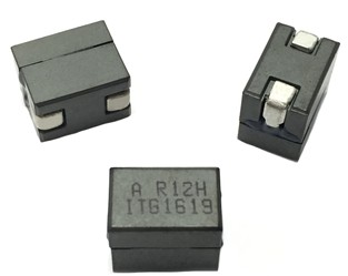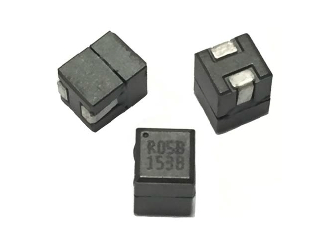
Product specifications
1. Open Circuit Inductance (OCL) Test Parameters: 100 kHz, 0.1 Vrms ,
0.0 Adc, +25 °C
2. Full Load Inductance (FLL) Test Parameters: 100 kHz, 0.1 Vrms , Isat1, +25 °C
3. I rms : DC current for an approximate temperature rise of 40 °C without core
loss. Derating is necessary for AC currents. PCB layout, trace thickness and
width, air-flow, and proximity of other heat generating components will affect
the temperature rise. It is recommended that the temperature of the part not
exceed +125 °C under worst case operating conditions verified in the end
application.
4. I sat1 : Peak current for approximately 20% (R10 10%) rolloff @
+25 °C (R10 10%)
5. I sat2: Peak current for approximately 20% (R10 10%) rolloff @ +85 °C
6. Isat3 : Peak current for approximately 20% (R10 10%) rolloff @ +100 °C
7. Isat4: Peak current for approximately 20% (R10 10%) rolloff @ +125 °C
8. K-factor: Used to determine Bp-p for core loss (see graph). Bp-p = K * L * ∆I.
Bp-p :(Gauss), K: (K-factor from table), L: (Inductance in µH),
∆I (peak to peak ripple current in amps).
9. Part Number Definition: FP1108Rx-yyy-R
- FP1108Rx = Product code and size
- Rx = DCR indicator
- yyy= Inductance value in µH
- “-R” suffix = RoHS compliant
Part Number9
OCL1
(nH) ±10%
FLL min.2
(nH)
I rms 3
(A)
I sat14
(A)
I sat25
(A)
I sat36
(A)
I sat47
(A)
DCR
(mΩ) @ +20 °C K-factor8
FP1108R1-R10-R 100 81
65
100+ 96 94 90
0.29±5%
330
FP1108R1-R15-R 150 110
77 72 66 63
330
FP1108R1-R18-R 180 132
65 61 58 50
330
FP1108R1-R21-R 210 151
55 51 48 45
330
Product Specifications
Part number9
OCL1
(nH) ±10%
FLL2 (nH)
minimum
I rms 3
(A)
Isat14
(A)
Isat25
(A)
I sat36
(A)
Isat47
(A)
DCR (mΩ)
@ +20°C
K-factor8
R1 version
FP1107R1-R07-R
70
50
55
140
na
na
123
0.29 ±8%
361.1
FP1107R1-R12-R
120
86
55
90
na
na
72
0.29 ±8%
361.1
FP1107R1-R15-R
150
108
55
70
na
na
56
0.29 ±8%
361.1
FP1107R1-R23-R
230
166
55
45
na
na
36
0.29 ±8%
361.1
FP1107R1-R30-R
300
217
55
35
na
na
28
0.29 ±8%
361.1
FP1107R1-R40-R
400
288
55
25
na
na
20
0.29 ±8%
361.1
FP1107R1-R51-R
510
364
55
18
na
na
14.5
0.29 ±8%
361.1
R2 version
FP1107R2-R07-R
70
50
42
140
na
na
123
0.47 ±6.4%
363.3
FP1107R2-R12-R
120
86
42
90
na
na
72
0.47 ±6.4%
363.3
FP1107R2-R15-R
150
108
42
70
na
na
56
0.47 ±6.4%
363.3
FP1107R2-R23-R
230
166
42
45
na
na
36
0.47 ±6.4%
363.3
FP1107R2-R30-R
300
217
42
35
na
na
28
0.47 ±6.4%
363.3
FP1107R2-R40-R
400
288
42
25
na
na
20
0.47 ±6.4%
363.3
FP1107R2-R51-R
510
364
42
18
na
na
14.5
0.47 ±6.4%
363.3
R4 version
FP1107R4-R180-R
180
130
50
62
55
53
50
0.29 ±5%
361
R5 version
FP1107R5-R070-R
70
50
55
140
na
na
123
0.29 ±5%
361.1
FP1107R5-R120-R
120
86
55
90
na
na
72
0.29 ±5%
361.1
FP1107R5-R150-R
150
108
55
70
na
na
56
0.29 ±5%
361.1
FP1107R5-R230-R
230
166
55
45
na
na
36
0.29 ±5%
361.1
FP1107R5-R300-R
300
217
55
35
na
na
28
0.29 ±5%
361.1
FP1107R5-R400-R
400
288
55
25
na
na
20
0.29 ±5%
361.1
FP1107R5-R510-R
510
364
55
18
na
na
14.5
0.29 ±5%
361.1
Number OCL1 ± 10% (nH) FLL2 Min. (nH) Irms
3 (Amps) Isat14 @ 25°C (Amps) Isat25 @ 125°C (Amps) DCR (mΩ) @ 20°C K-factor6
FP1105R1-R10-R 100
72
81
63
467
FP1105R1-R12-R 120
Part Number8
OCL1
(nH) ±10%
FLL2 (nH)
minimum
Irms 3
(amps)
Isat14
(amps)
Isat25
(amps)
Isat36
(amps)
DCR (mΩ)
±10% @ 20°C
K-factor7
L1 Version
FP1108L1-R105-R
105
76
64
81
77
72
0.10
422
FP1108L1-R150-R
150
108
64
57
49
45
0.10
422
FP1108L1-R180-R
180
129
64
47
41
37
0.10
422
L2 Version
FP1108L2-R150-R
150
108
48
55
50
46
0.18
390
86
66
50
467
FP1105R1-R15-R 150
109
46
54
42
0.35 ± 8.6% 467
FP1105R1-R20-R 192
138
42
34
467
FP1105R1-R22-R 226
163
39
28
467
Part number9
OCL1
(nH)
FLL2 (nH)
minimum
I rms 3
(A)
Isat14
(A)
Isat25
(A)
I sat36
(A)
Isat37
(A)
DCR (mΩ)
±5% @ 20°C
K-factor8
Dimension
C (mm)
maximum
FP1010R1-R120-R
120 ±15%
84
50
94
na
80
75
0.185
371
10
FP1010R1-R150-R
150 ±15%
105
50
80
na
68
64
0.185
371
10
FP1010R1-R330-R
330 ±15%
230
50
30
na
25
23
0.185
371
10
FP1010R3-R070-R
70 ±10%
50
78
124
120
115
107
0.145
432
10.4
FP1010R3-R100-R
100 ±10%
72
78
95
88
82
77
0.145
432
10.2
FP1010R3-R120-R
120 ±10%
86
78
78
71
67
63
0.145
432
10.1
FP1010R3-R150-R
150 ±10%
100
78
60
54
52
49
0.145
432
10
FP1010R3-R180-R
180 ±10%
129
78
49
45
43
40
0.145
432
10
FP1010R3-R220-R
220 ±10%
158
78
38
36
34
31
0.145
432
10
FP1010R3-R270-R
270 ±10%
194
78
30
29
27
24
0.145
432
10
FP1010R3-R300-R
300 ±10%
210
78
27
24
23
22
0.145
432
10
FP1010R3-R330-R
330 ±15%
237
78
20
19
17
16
0.145
432
10
Part Number8
OCL1
(nH) ±10%
FLL2
(nH) minimum
Irms 3
(A)
I sat14
(A)
I sat25
(A)
Isat36
(A)
DCR (mΩ)
maximum @ 20°C
K-factor7
FP1008R7-R100-R
100
72
72
100
90
84
0.120
361
FP1008R7-R120-R
120
86
72
90
75
70
0.120
361
FP1008R7-R150-R
150
108
72
72
60
56
0.120
361
FP1008R7-R180-R
180
130
72
60
50
46
0.120
361
Product specifications
Part number8
OCL1
(nH) ±10%
FLL2 (nH)
minimum
I rms 3
(A)
Isat14
(A)
Isat25
(A)
Isat36
(A)
DCR (mΩ)
@ +20 °C
K-factor7
V1 Version
FP1010V1-R100-R
100
72
68
97
88
85
0.145 ±5%
352
FP1010V1-R120-R
120
86
68
80
73
71
0.145 ±5%
352
FP1010V1-R150-R
150
108
68
65
59
57
0.145 ±5%
352
FP1010V1-R180-R
180
130
68
53
48
46
0.145 ±5%
352
V4 Version
FP1010V4-R330-R
330
230
34
35
33
30
0.40 ±5%
216
V5 Version
FP1010V5-R100-R
100
72
68
117
97
94
0.185 ±10%
308
FP1010V5-R120-R
120
86
68
98
82
79
0.185 ±10%
308
FP1010V5-R150-R
150
108
68
85
75
73
0.185 ±10%
308
FP1010V5-R330-R
330
237
68
35
29
27
0.185 ±10%
308
V6 Version
FP1010V6-R330-R
330
231
54
40
32
30
0.40 ±5%
216
FP1010V6-R470-R
470
329
54
30
22
21
0.40 ±5%
216
1. Open circuit inductance (OCL) Test parameters: 100 kHz, 0.1 Vrms, 0.0 Adc, +25 °C
2. Full load inductance (FLL) Test parameters: 100 kHz, 0.1 Vrms, Isat1, +25 °C
3. Irms : DC current for an approximate temperature rise of 40 °C without core loss. Derating is
necessary for AC currents. PCB layout, trace thickness and width, air-flow, and proximity of other heat
generating components will affect the temperature rise. It is recommended that the temperature of the
part not exceed +125 °C under worst case operating conditions verified in the end application.
4. Isat1: Peak current for approximately 20% rolloff @ +25 °C
5. Isat2: Peak current for approximately 20% rolloff @ +75 °C (FP1010V1), @ +100 °C (FP1010V4, V5, V6)
6. Isat3: Peak current for approximately 20% rolloff @ +100 °C (FP1010V1), @ +125 °C (FP1010V4, V5, V6)
7. K-factor: Used to determine Bp-p for core loss (see graph).
Bp-p = K * L * ΔI * 10-3 Bp-p: (Gauss), K: (K-factor from table),
L: (Inductance in nH), ΔI (Peak to peak ripple current in Amps).
8. Part number definition: FP1010Vx-Rxxx-R
FP1010V= Product code and size
x= Version indicator
Rxxx= Inductance value in μH, R= decimal point
-R suffix = RoHS compliant
Part number8
OCL1
(nH) ±10%
FLL2
(nH) minimum
Irms 3
(A)
Isat14
(A)
Isat25
(A)
Isat36
(A)
DCR (mΩ)
@ +20 °C
±10%
K-factor7
V2 version
FP1012V2-R070-R
70
50
84
130+
130+
130+
0.125
305
FP1012V2-R080-R
80
57
84
130+
130+
125
0.125
305
FP1012V2-R090-R
90
64
84
130+
117
110
0.125
305
FP1012V2-R100-R
100
72
84
125
105
100
0.125
305
FP1012V2-R120-R
120
86
84
105
88
81
0.125
305
FP1012V2-R150-R
150
108
84
83
70
66
0.125
305
FP1012V2-R330-R
330
231
84
36
28
26
0.125
305
FP1012V2-R470-R
470 (±15%)
329
84
22
19
18
0.125
305
V3 version
FP1012V3-R070-R
70
50
84
190
172
160
0.125
305
FP1012V3-R080-R
80
57
84
170
146
132
0.125
305
FP1012V3-R090-R
90
64
84
150
128
121
0.125
305
FP1012V3-R100-R
100
72
84
138
115
110
0.125
305
FP1012V3-R120-R
120
86
84
116
96
89
0.125
305
FP1012V3-R150-R
150
108
84
91
77
72
0.125
305
FP1012V3-R240-R
240
168
84
56
48
45
0.125
305
FP1012V3-R330-R
330
231
84
40
32
30
0.125
305


