(Amps) @+125 °C
@+20 °C
K-factor6
FP1505R1-R10-R 100
72
105
90
356.3
FP1505R1-R12-R 120
86
87
75
356.3
FP1505R1-R15-R 150
108
53
72
60
0.47 ± 7%
356.3
FP1505R1-R25-R 250
180
42
32
356.3
FP1505R1-R30-R 300
217
35
26
356.3
FP1505R1-R40-R 400
288
24
19.5
356.3
P
Technical Data 4355
Effective June 2017
www.eaton.com/electronics
Packaging information - mm
Dimensions- mm
1 Open Circuit Inductance (OCL) Test Parameters: 100kHz, 1.0Vrms, 0.0Adc
2 Full Load Inductance (FLL) Test Parameters: 100kHz, 1.0Vrms, I sat1.
3 I rms: DC current for an approximate temperature rise of 40°C without core loss. Derating is
necessary for AC currents. PCB pad layout, trace thickness and width, air-flow and proximity of other heat
generating components will affect the temperature rise. It is recommended the part temperature not exceed
125°C under worst case operating conditions verified in the end application.
4 I sat: Peak current for approximately 20% rolloff at +25°C.
5 Isat2: Peak current for approximately 20% rolloff at +125°C.
6 K-factor: Used to determine Bp-p for core loss (see graph). Bp-p = K * L * ΔI * 10-3. Bp-p (Gauss),
K: (K-factor from table), L: (inductance in nH), ΔI (peak-to-peak ripple current in amps).
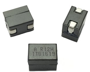
7 Part Number Definition: FP1308Rx-Rxx-R
• FP1308 = Product code and size
• Rx = DCR indicator
• Rxx = Inductance value in μH, R = decimal point.
• “-R” suffix = RoHS compliant
Product Specifications
Part
OCL
1
FLL2
I rms3
I sat14
I sat25
DCR (mΩ)
Number
7
± 10% (nH) (nH) (Amps) @ 25°C (Amps) @ 125°C (Amps) @ 20°C K-factor6
R1 Version
FP1308R1-R11-R 110 79
120
105
233
FP1308R1-R21-R 210 152
80
68
233
FP1308R1-R26-R 260 187 57
64
52
0.32 ± 9.4% 233
FP1308R1-R32-R 320 230
52
40
233
FP1308R1-R44-R 440 317
37
28
233
R2 Version
FP1308R2-R11-R 110 79
120
105
233
FP1308R2-R21-R 210 152
80
68
233
FP1308R2-R26-R 260 187 45
64
52
0.53 ± 10% 233
FP1308R2-R32-R 320 230
52
40
233
FP1308R2-R44-R 440 317
37
28
233
R3 Version
FP1308R3-R11-R 110 79
120
105
233
FP1308R3-R21-R 210 152
80
68
233
FP1308R3-R26-R 260 187 68
64
52
0.18 ± 20% 233
FP1308R3-R32-R 320 230
52
40
233
FP1308R3-R44-R 440 317
37
28
233
Technical Data 4366
Effective June 2017
www.eaton.com/electronics
Packaging information - mm
Dimensions- mm
1 Open Circuit Inductance (OCL) Test Parameters: 100kHz, 0.1Vrms, 0.0Adc
2 Full Load Inductance (FLL) Test Parameters: 100kHz, .01Vrms, Isat1
3 Irms: DC current for an approximate temperature rise of 40°C without core loss. Derating is
necessary for AC currents. PCB layout, trace thickness and width, air-flow, and proximity of other
heat generating components will affect the temperature rise. It is recommended that the
temperature of the part not exceed 125°C under worst case operating conditions verified in the
end application.
4 Isat1: Peak current for approximately 20% rolloff at +25°C.
5 Isat2: Peak current for approximately 20% rolloff at +125°C.
6 K-factor: Used to determine Bp-p for core loss (see graph). Bp-p = K * L * ΔI * 10-3. Bp-p:(Gauss), K:
(K-factor from table), L: (Inductance in nH), ΔI (Peak-to-peak ripple current in amps).
7 Part Number Definition: FP1206Rx-Rxx-R
• FP1206 = Product code and size
• Rx= DCR indicator
• Rxx= Inductance value in uH, R = decimal point
• -R suffix = RoHS compliant
Product Specifications
Part
OCL1
FLL2
I rms
3
I sat14
I sat25
DCR (mΩ)
Number7
± 10% (nH) Min. (nH) (Amps) (Amps) @25°C (Amps) @125°C @20°C K-factor6
FP1206R1-R12-R 120
86
88
65
358
FP1206R1-R15-R 150
108
70
51
358
FP1206R1-R25-R 250
180
50
43
32 0.43 ± 6.5% 358
FP1206R1-R30-R 300
216
34
26
358
FP1206R1-R40-R 400
288
24
19
358
Part number7
OCL1
(nH) ±10%
FLL2 (nH)
minimum
Irms3
(A)
Isat14
(A)
Isat25
(A)
DCR (mΩ)
±5% @ +20°C
K-factor6
V1 version
FP1110V1-R15-R
150
108
61
90
72
0.23
278
FP1110V1-R20-R
195
140
61
70
58
0.23
278
FP1110V1-R22-R
220
158
61
64
51
0.23
278
FP1110V1-R27-R
270
173
61
55
44
0.23
278
FP1110V1-R32-R
320
230
61
42
34
0.23
278
V2 version
FP1110V2-R150-R
150
108
61
89
70
0.18
328
FP1110V2-R180-R
180
130
61
72
57.5
0.18
328
FP1110V2-R200-R
200
144
61
65
52
0.18
328
FP1110V2-R220-R
220
159
61
59
47
0.18
328
FP1110V2-R270-R
270
195
61
48
38.5
0.18
328
FP1110V2-R320-R
320
230
61
40.5
32.5
0.18
328
Product Specifications
Part Number7
OCL1 ± 20% (nH) FLL2 Min. (nH) Irms
3 (Amps) Isat14 @ 25°C (Amps) Isat25 @ 125°C (Amps) DCR (mΩ) @ 20°C K-factor6
FP1109-R20-R
205
122
69
52
233
FP1109-R23-R
247
147
55
41
233
FP1109-R27-R
270
160
51
38
233
FP1109-R33-R
311
185
35
44
33
0.42 ±10% 233
FP1109-R47-R
463
275
27
20
233
FP1109-R58-R
548
325
22.5
17
233
FP1109-1R0-R
950
565
11.5
8.5
233
Product specifications
Part Number7
OCL1
(nH)±10%
FLL2
(nH) minimum
Irms 3
(A)
Isat14
(A)
Isat25
(A)
DCR (mΩ)
@ +20 °C ±5%
K-factor8
FP1109B1-R150-R
150
108
55
80
64
0.19
339
FP1109B1-R180-R
180
130
55
62
49
0.19
339
FP1109B1-R220-R
220
158
55
50
40
0.19
339
FP1109B1-R300-R
300
216
55
38
30
0.19
339
FP0705R2-R07-R
FP0705R1-R15-R
FP0705R2-R10-R
FP0705R1-R22-R
FP0505R1-R100-R
FP0705R1-R18-R
FP0507V1-R050-R
FP0607V1-R050-R
FP0705R1-R07-R
Product specifications
Part Number7
OCL1
(nH) ±10%
FLL2
(nH) minimum
Irms 3
(A)
Isat14
(A)
I sat25
(A)
DCR (mΩ)
@ 20°C
K-factor7
R1 version
FP0705R1-R07-R
72
51
43
65
50
0.25 ± 10%
826
FP0705R1-R10-R
105
78
43
44
34
0.25 ± 10%
826
FP0705R1-R12-R
120
86
43
37
30
0.25 ± 10%
826
FP0705R1-R15-R
150
108
43
30
24
0.25 ± 10%
826
FP0705R1-R18-R
180
130
43
25
20
0.25 ± 10%
826
FP0705R1-R22-R
226
159
43
20
16
0.25 ± 10%
826
R2 version
FP0705R2-R07-R
72
51
38
65
50
0.32 ± 9.4%
826
FP0705R2-R10-R
105
78
38
44
34
0.32 ± 9.4%
826
FP0705R2-R12-R
120
86
38
37
30
0.32 ± 9.4%
826
FP0705R2-R15-R
150
108
38
30
24
0.32 ± 9.4%
826
FP0705R2-R18-R
180
130
38
25
20
0.32 ± 9.4%
826
FP0705R2-R22-R
226
159
38
20
16
0.32 ± 9.4%
826
R2 version
FP0705R3-R07-R
72
51
32
65
50
0.46 ± 6.5%
826
FP0705R3-R10-R
105
78
32
44
34
0.46 ± 6.5%
826
FP0705R3-R12-R
120
86
32
37
30
0.46 ± 6.5%
826
FP0705R3-R15-R
150
108
32
30
24
0.46 ± 6.5%
826
FP0705R3-R18-R
180
130
32
25
20
0.46 ± 6.5%
826
FP0705R3-R22-R
226
159
32
20
16
0.46 ± 6.5%
826
Product specifications
Part number5
OCL1
(nH) ±15%
FLL2
(nH) minimum
Irms 3
(A)
Isat14
(A)
Isat25
(A)
Isat36
(A)
DCR (mΩ)
@ +20 °C
±25%
K-factor7
FP0404R1-R022-R
22 ±20%
15
40
40
34
32
0.32 ± 15%
2351
FP0404R1-R065-R
65
44
40
24
22
20
0.32
2248
FP0404R1-R080-R
80
54
40
19.5
18
16
0.32
2248
FP0404R1-R100-R
100
68
40
15.6
14
13
0.32
2248
FP0404R1-R110-R
110
74.5
40
14.2
13
11.8
0.32
2248
FP0404R1-R170-R
170
116
40
9.0
7.8
7.6
0.32
2248
FP0404R1-R022-R
Product specifications
Part number5
OCL1 (μH)
±15%
lrms2 (amps)
lsat3 (amps)
DCR (Ω) typical
@ 20°C
DCR (Ω) maximum
@ 20°C
Volt-μsec4
(V-usec)
FP4-100-R
0.100
40
64
0.00038
0.00065
1.33
FP4-120-R
0.120
40
54
0.00038
0.00065
1.33
FP4-150-R
0.150
40
42
0.00038
0.00065
1.33
FP4-200-R
0.200
40
30
0.00038
0.00065
1.33
Product Specifications
Function Specifications
Test Specifications
Part Number4,5
Inductor
phases
DCR (Ω)
±10%
@25°C
Rated
Inductance
per Phase3
(nH)
I Rated per
Phase3 (ADC)
Imax Peak
per Phase3
(ADC)
Pin
numbers
OCL1,2
(nH)
Pin
numbers
OCL1,2
(nH)
Magnetizing
Inductance2
(nH) @ 10ADC
(25°C)
CPL2-2-50TR-R
2
0.00028
50 ± 20%
50
80
(1-2)
380±20%
(3-4)
380±20%
300
CPL2-3-50TR-R
3
0.00028
50 ± 20%
50
80
(3-4)
400±20%
(1-2), (5-6)
380±20%
300
CPL2-4-50TR-R
4
0.00028
50 ± 20%
50
80
(3-4), (5-6)
400±20%
(1-2), (7-8)
380±20%
300
CPL2-5-50TR-R
5
0.00028
50 ± 20%
50
80
(3-4), (5-6), (7-8)
400±20%
(1-2), (9-10) 380±20%
300
1. OCL (Open Circuit Inductance)
2. Test parameters: 1MHz, 0.1Vrms, 0.0Adc. @25°C
3. The rated current and rated inductance per phase is determined by Volterra’s testing and circuit design. Additional
information can be provided by contacting Volterra.
4. Part Number Definition: CPL2-x-50TR-R
• CPL2= Product code and size
• -x= number of phases
• -50 = rated inductance value per phase in nH
• TR= Tape and reel
• -R suffix= RoHS compliant
5. This device is licensed for use only when incorporated within a voltage regulator employing power reg