ER-008638
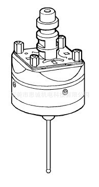
Probe with ball ø5 mm
ER-010562
Probe with ball ø2 mm
For safety, guarantee, liability
and service addresses, see
Appendix A.
Note:The probe is a very
accurate measuring instrument
and must be treated with the
appropriate cleanness. If the
probe shows any signs of
improper handling, hits or any
subsequent machining, this
shall preclude any claims to
indemnification under
guarantee.
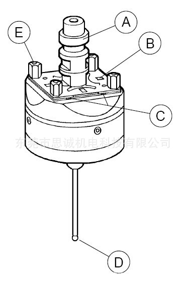
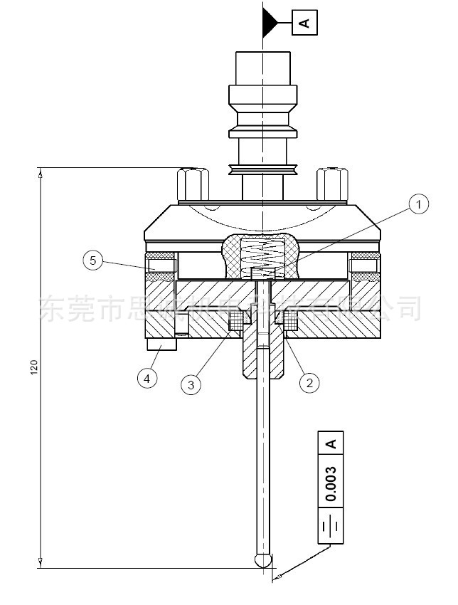
Description of parts
A) Chucking spigot
B) Centering plate
C) Reference mark
D) Probe pin with
ball ø 5 mm or ø 2 mm
E) Supporting feet
Note: Neither loosen nor
retighten the support feet.
Application
Automatic aligning
of workpieces on CNC
EDM machines.
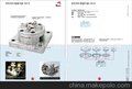
Technical data
1) Bolt M4 x 16
2) Adjustment washer
3) Sealing ring
4) Bolts M5 x 30
5) Threaded pins
 Setting up
Clamp the probe into an ITS
chuck in relation to the
reference side. Start the
measuring /aligning program
of the CNC machine.
The rotation axis may be run
at low revolutions. The probe
works on the principle of
electric contact. However, it
has an overshoot protection of
1 mm in the X- and Y-axes and
of 0.5 mm in the Z-axis. Carry
out the desired measurement.
When doing so, take into
account the ball diameter.
Note:The concentricity of the
probe should be checked from
time to time, and corrected if
necessary.
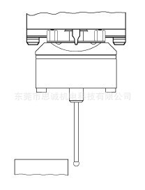
This is done most easily on
an ITS measuring station or
an equivalent facility with a
flat-contact probe (no ball).
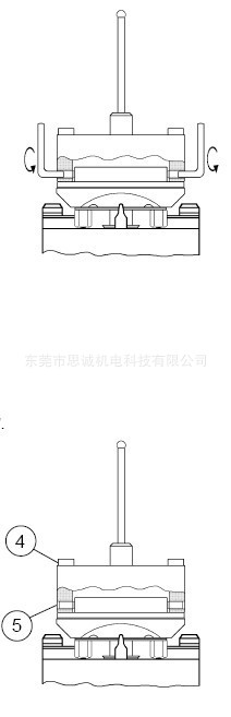
Lightly loosen the three bolts
(4) so that the U-washers
remain in place.
Correct concentricity with the
four threaded pins (5). To do
so quickly and accurately, the
following points must be
observed:
Point 1:
Correcting in the 0°-180° axis.
Set the dial gauge to zero at 0°
or 180°. Turn probe round 180°
to make the deviation visible on
the dial gauge so that it can be
corrected. When correcting
concentricity, halve this value
and move the probe into the
centre with the threaded pins.
Always use two opposite pins
for the purpose.
How to proceed:
Loosen one pin, tighten the
opposite pin. After the
correction has been completed,
give the two threaded pins a
slight turn in the same direction
and proceed to the next step.
Point 2:
Correcting in the 90°-270° axis.
Turn the probe round 90° and
set the dial gauge to zero at
90° or 270°. Determine the
deviation, then correct
concentricity as in Point 1.
Point 3:
When you have achieved the
desired precision (0.003 mm),
lightly tighten bolts (4). Check
concentricity again and correct
if necessary. To this purpose,
the whole "How to correct
concentricity" process must be
repeated.
Finally, gradually tighten bolts
(4) until you reach a torque of
5 Nm. Give the threaded pins a
slight turn in the same direction.
Check concentricity.
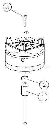
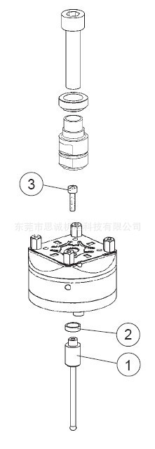
Replace probe pin
If the probe pin should break,
it can be replaced in a simple
manner:
- Remove chucking spigot
- Loosen bolt (3) through
the M10 thread with a hex
key.
- Pull out probe pin (1).
Caution: Do not lose the
spacer (2).
- Insert replacement probe
pin into spacer (2) and
fasten with bolt (3) to a
torque of 3.5 Nm.
- Attach chucking spigot.
- Set concentricity (see
"How to correct concentricity").
Malfunctions,
trouble-shooting
E=Error, C=Cause,
R=Remedy
E : Probe is not concentric.
C : a) Chucking spigot mounted
in the wrong way.
b) Probe damaged.
R : a) Mount chucking spigot
according to the manual.
b) -Replace probe pin.
-Check concentricity.
-Return probe to your
EROWA representative
for repair.
Spare parts
ER-010560
Replacement probe pin ø 5 mm
ER-010561
Replacement probe pin ø 2 mm
思诚机电科技有限公司主要销售以下产品:
瑞士EROWA 柔性加工定位夹具
德国BLUM产品系列,CNC用激光对刀仪、接触式对刀器、在线测量探头
美国VEKTEK液压夹具系列
电加工耗材系列(韩国纸芯过滤器、铜线等)
以色列NOGA万向磁性表座、刮刀,手动去毛刺系列
瑞士GIROD-TAST红宝石杠杆表
台湾Toltel影像影像显微量测仪(TTC放大镜)