Features
• Support for all Lattice programmable products
– 1.2V to 5V programming
– Ideal for design prototyping and debugging
• Connect to multiple PC interfaces
– USB (v.1.0, v.2.0)
– PC Parallel Port
• Easy-to-use programming connectors
• Versatile flywire, 2 x 5 (.100”) or 1 x 8 (.100”) connectors
• 6 feet (2 meters) or more of programming cable length (PC to DUT)
• Lead-free/RoHS compliant construction
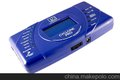
Figure 1. USB Cable – HW-USBN-2A (Parallel Cable - HW-DLN-3C Not Shown)

ispDOWNLOAD Cables
Lattice ispDOWNLOAD® Cable products are the hardware connection for in-system programming of all Lattice devices. After completion of the logic design and creation of a programming file with the Lattice Diamond®, isp-LEVER® Classic or PAC-Designer® software, the Lattice Diamond Programmer, or Lattice's ispVM™ System soft-ware is used to control the programming of devices directly on the PC board. No additional components are required to program a device.
After you complete your logic design and create a programming file with the Lattice Diamond/ispLEVER develop-ment tools, you can use ispVM™ System software or Diamond Programmer to program devices on your board. The ispVM System/Diamond Programmer software automatically generates the appropriate programming com-mands, programming addresses and programming data based on information stored in the programming file and parameters you set in ispVM/Diamond Programmer. Programming signals are then generated from the USB or par-allel port of a PC and directed through the ispDOWNLOAD Cable to the device. No additional components are required for programming.
ispVM System/Diamond Programmer software is included with all Lattice design tool products and is available for download from the Lattice web site at www.latticesemi.com.
![]()
2
 Lattice Semiconductor ispDOWNLOAD Cables
![]()
ispDOWNLOAD Cable Pin Definitions
The functions provided by the ispDOWNLOAD cables correspond with available functions on Lattice programmable devices. Since some devices contain different programming features, the specific functions provided by the isp-DOWNLOAD cable may depend on the selected target device. ispVM System/Diamond Programmer software will automatically generate the appropriate functions based on the selected device. See Table 1 for an overview of the ispDOWNLOAD cable functions.
Table 1. ispDOWNLOAD Cable Pin Definitions
ispDOWNLOAD | ispDOWNLOAD Cable | ||||
Cable Pin | Name | Pin Type | Description | ||
Connect to VCC or VCCJ plane of the target device. Typical | |||||
VCC | Programming Voltage | Input | ICC = 10mA. Your board design supplies the power for | ||
VCC. Note: This may not be the same as a target device’s | |||||
VCCO plane. | |||||
SDO/TDO | Test Data Output | Input | Used to shift data out via the IEEE1149.1 (JTAG) | ||
programming standard. | |||||
SDI/TDI | Test Data Input | Output | Used to shift data in via the IEEE1149.1 programming | ||
standard. | |||||
ispEN/Enable/ | Enable | Output | Enable device to be programmed. | ||
PROG | |||||
TRST | Test Reset | Output | Optional IEEE 1149.1 state machine reset. | ||
DONE | DONE | Input | DONE indicates status of configuration | ||
MODE/TMS | Test Mode Select Input | Output | Used to control the IEEE1149.1 state machine. | ||
GND | Ground | Input | Connect to ground plane of the target device | ||
SCLK/TCK | Test Clock Input | Output | Used to clock the IEEE1149.1 state machine | ||
INIT | Initialize | Input | Indicates that ORCA® device is ready for configuration. | ||
Figure 2. ispDOWNLOAD Cable In-System Programming Interface for the PC (HW-USB-1A or HW-USB-2A)1
Function | Color | |||||||||||||||||
VCC | Red | |||||||||||||||||
SDO/TDO | Brown | |||||||||||||||||
SDI/TDI | Orange | |||||||||||||||||
Yellow | ||||||||||||||||||
To | ispEN/Enable/PROG | To | ||||||||||||||||
PC | TRST/DONE | Green | System | |||||||||||||||
MODE/TMS | Purple | Board | ||||||||||||||||
6' | HW-USB-1A | GND | Black | |||||||||||||||
SCLK/TCK | White | |||||||||||||||||
INIT | Blue | |||||||||||||||||

1. Lattice PAC-Designer® software does not support programming with USB cables. To program ispPAC devices with these cables, use the ispVM System software/Diamond Programmer.
Figure 3. ispDOWNLOAD Cable In-System Programming Interface for the PC (HW-DLN-3C and Equivalents)1
HW7265-DL3 and HW7265-DL3A – Grey Housing with RJ-45 Connector
Other Cables are Labeled with Part Number

To | 25-pin | |
Parallel | ||
PC | Port | |
Adapter | 6' | |
![]()
Function | Color | ||||
VCC | Red | ||||
SDO/TDO | Brown | ||||
SDI/TDI | Orange | ||||
Yellow | To | ||||
ispEN/Enable/Prog | |||||
TRST | Green | System | |||
Board | |||||
MODE/TMS | Purple | ||||
GND | Black | ||||
SCLK/TCK | White | ||||
![]()
1. HW7265-DL3, HW7265-DL3A, HW-DL-3B, HW-DL-3C and HW-DLN-3C are functionally equivalent products.
![]()
3
Lattice Semiconductor ispDOWNLOAD Cables
![]()
Figure 3. ispDOWNLOAD Cable In-System Programming Interface for the PC (pDS4102-DL2 or pDS4102-DL2A)
pDS4102-DL2 – Blue Housing | End View | ||||||||
pDS4102-DL2A – Grey Housing | Function | Pin # | |||||||
| .100" Center-Spacing | VCC | 1 | ||||||
SDO/TDO | 2 | ||||||||
RJ-45 Connector | Eight Positions | ||||||||
SDI/TDI | 3 | ||||||||
25-pin | Eight Positions | ||||||||
To | |||||||||
To | ispEN/Enable/PROG | 4 | |||||||
Parallel | |||||||||
System | |||||||||
PC | Port | .01µf* | TRST | 5 | |||||
Board | |||||||||
Adapter | 6' | Capacitor | MODE/TMS | 6 | |||||
GND | 7 | ||||||||
SCLK/TCK | 8 | ||||||||
Note: Capacitor Recommended on System Board | |||||||||

![]()
![]()
![]()
Figure 4. Figure 4. ispDOWNLOAD Cable In-System Programming Interface for the PC (HW7265-DL2 or HW7265-DL2A)
HW7265-DL2 – Blue Housing | Overhead View of PC Board | ||||||||||
HW7265-DL2A – Grey Housing | |||||||||||
End View1 | ConnectorPinout | ||||||||||
Pin # | Function | Function | Pin # | Pin # | Function | Function | Pin # | ||||
RJ-45 Connector | 2 | GND | SCLK/TCK | 1 | 1 | SCKL/TCK | GND | 2 | |||
To | 25-pin | Eight Positions | 4 | GND | MODE/TMS | 3 | To | 3 | MODE/TMS | GND | 4 |
Parallel | 6 | VCC | SDI/TDI | 5 | 5 | SDI/TDI | VCC | 6 | |||
System | |||||||||||
PC | |||||||||||
Port | 8 | GND | SDO/TDO | 7 | Board | 7 | SDO/TDO | GND | 8 | ||
Adapter | |||||||||||
6' | 10 | ispEN/Enable/ | TRST | 9 | 9 | TRST | ispEN/Enable/ | 10 | |||
PROG | PROG | ||||||||||

1. For reference purposes, the 2x10 connector on the HW7265-DL2 or HW7265-DL2A is equivalent to Tyco 102387-1. This will interface to standard 100-mil spacing 2x5 headers, or a 2x5 keyed, recessed male connector such as the 3M N2510-5002RB.
Programming Software
ispVM System/Diamond Programmer is the preferred programming management software tool for all Lattice devices and download cables. The latest version of ispVM System software or the Lattice Diamond Program-mer is available for download from the Lattice web site at www.latticesemi.com/software.
Target Board Design Considerations
A 4.7K pull-down resistor is recommended on the TCK connection of the target board. This pull-down is recom-mended to avoid inadvertent clocking of the TAP controller induced by fast clock edges or as VCC ramps up. This pull-down is recommended for all Lattice programmable families.
For Lattice device families that feature low power, it is recommended to add a 500 ohm resistor between VCCJ and GND during the programming interval when a USB ispDOWNLOAD cable is connected to a very low power board design. A FAQ is available that discusses this in more depth at: www.latticesemi.com/support/faqs/details.cfm?id=2205
The JTAG programming port speed may need to be governed when using the ispDOWNLOAD cables connected to customer PCBs. This is especially important when there is long PCB routing or with many daisy-chained devices. The Lattice programming software can adjust the timing of TCK applied to the JTAG programming port from the cable. This low-precision port setting of TCK depends on many factors, including the PC speed and the type of cable used (parallel port, USB or USB2). This software feature provides an option to slow the TCK for debug or noisy environments. A FAQ is available that discusses this in more depth at: www.latticesemi.com/support/faqs/details.cfm?id=974
The USB Download Cable can be used to program Power Manager or ispClock products with Lattice programming software. When using the USB cable with the Power Manager I devices, (POWR604, POWR1208, POWR1208P1), you must slow do TCK by a factor of 2. A FAQ is available that discusses this in more depth at: www.latticesemi.com/support/faqs/details.cfm?id=306
![]()
4
Lattice Semiconductor ispDOWNLOAD Cables
![]()
Programming Flywire and Connection Reference
Refer to Table 2 when connecting a flywire download cable to systems that use the 1x8-position or 2x5-position connectors. For newer Lattice FPGA families, a 1x10 connector used in conjunction with the ispDOWNLOAD USB cable adds support for the DONE and INITN signals. Both of these signals are inputs to the cable, and can be used to help verify device configuration.
Table 2. Flywire Conversion Reference
Function | Flywire Cable | 1x10 Connector | 1x8 Connector | 2x5 Connector | ||
1 | Red | 1 | 1 | 6 | ||
VCC | ||||||
TDO/SDO | Brown | 2 | 2 | 7 | ||
TDI/SDI | Orange | 3 | 3 | 5 | ||
2/Enable/PROGRAMN | Yellow | 4 | 4 | 10 | ||
ispEN | ||||||
TRST3 | Green | 5 | 5 | 9 | ||
TMS/MODE | Purple | 6 | 6 | 3 | ||
GND | Black | 7 | 7 | 4 (2 and 8) | ||
TCK4/SCLK | White | 8 | 8 | 1 | ||
DONE3 | Green | 9 | ||||
INITN | Blue | 10 | ||||
1. For devices that have a VCCJ pin, the VCCJ must be connected to the cable’s VCC, and a 0.1µF decoupling capacitor is required on VCCJ close to the device. Please refer to the device data sheet to determine if the device has a VCCJ pin.
2. For older Lattice ISP devices, a 0.01µF decoupling capacitor is required on ispEN/ENABLE of the target board.
3. The TRST and DONE pin is multiplexed on the ispDOWNLOAD USB cable. If the device TRST signal is available on the board, connect the USB flywire TRST/DONE wire to TRST. If the device DONE signal is available on the board (or if both TRST and DONE are available), con-nect the USB flywire TRST/DONE wire to DONE. Please make sure the correct setting is selected in ispVM/Diamond Programmer (Options, Cable and I/O Port Setup). This will tell ispVM/Diamond Programmer whether the TRST/DONE cable is used as a TRST or a DONE signal.
4. A 4.7K pull-down resister is recommended on TCK of the target board.
![]()
Table lists the recommend pin connections. Please contact Lattice technical support for information on unlisted device families. (e-mail: techsupport@latticesemi.com, phone: 1-800-LATTICE).
***************************************************
联 系 人 ;雷 俊 (先 生)
深圳博瑞图电子科技有限公司
TEL:0755-36675904
MOB:13823138950
FAX:0755-83244576
ADD:深圳市福田区中航路世纪汇都会轩1416室
EMAIL: 401512450@qq.com
网 址:www.szprotools.com
***************************************************
承接销售元器件IC一条龙、专注10年