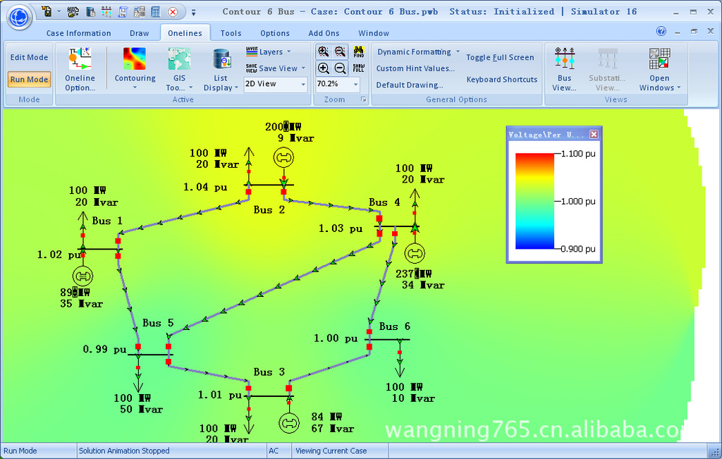
供应Powerworld Simulator 16 电力仿真软件

西安勒让德电子科技有限公司
中国 西安
产品属性
图文详情
品牌推荐
品牌
Powerworld
软件名称
Powerworld Simulator 16
软件类型
电力行业专用仿真软件
版本类型
单机版
语言版本
英文版
版本号
16
配套附件
技术文档
平台要求
xp
系统硬件要求
p4以上
技术支持
文档类
- itsintuitive menusfor assigning dynamic models to power system elements,
- constucting fault timelines and running the simulation,
- and plotting results;
New Add-on
- Distributed Transient Stability: extension ofDistributed Computingfeatures for parallel computation ofTransient Stabilitycontingencies
Auxiliary Files and Display Auxiliary Files
- TheSelectedfield can now be used with oneline display objects in Display Auxiliary Files.
Available Transfer Capability (ATC)
- Optimized the speed of the ATC calculations. Overall speed increase from the initial release of Simulator 15 is now between 2 and 6 times for the iterated solution methods and between 4 and 10 times for the Single Linear Step solution methods.
- Added a new Added a new option to linearize the calculation of contingency makeup power. This will precalculate the impact of makeup power on line flows at the start of the analysis and then the total effect of makeup power will be determined by multiplying the effect on a line by the Total amount of Makeup power needed. This calculation will be slightly faster than previous calculation of makeup power, but it will not take into account the fact larger amounts of makeup power may cause particular generators to hit min or max limits.
- Removed the optionApply PTDF Cutoff for Limiting Elements with Contingencies.
- Added a new option for the ATC calculation when performing the calculation on multiple scenarios. The option will allow you to specify that monitoring be done only on branches that are defined as part of the scenarios.
- Added optionAdded option to select theField to Showon the multiple scenarios results summary table.
- Modified theModified thehighlighting used and Iteratively Foundstring for better understanding of the results when using iterated methods.
- Removed the Removed theMax Iterationsoption when using the iterated methods. This is no longer necessary as oscillation prevention is handled internally.
Contingency Analysis
- Two different types of fields are now available with contingencies to list the Areas/Zones/Owners associated with the elements of the contingency. Fields exist for listing either the number or name of the associated Areas/Zones/Owners. Fields that are labeled with “recurse� will look inside injection groups, interfaces, and contingency blocks for identifying the associated Areas/Zones/Owners. Fields without “recurse� will not look inside injection groups, interfaces, or contingency blocks.
- Added option to use labels in contingency action descriptions. This includes actions shown in theContingency Definition listandWhat Actually Occurred. This can be useful when used with a full-topology EMS model.
- When listing contingency results by element (bus, branch, interface, nomogram interface, or custom monitor), only those elements which actually have a violation are now listed
- Specific generators, loads, and switched shunts can now be specified in addition to buses when usingMove, Set To, and Change Byactions.
- Added an optional "inclusion filter" with eachContingency Global Actions Elements. The global action will only be used with a particular contingency only if the contingency meets the inclusion filter.
- Added newCustom Monitoringto the contingency analysis tool. This allows you to setup monitoring of a field of a specific object (or all objects of a specific type) and report these fields values as limit violations in the contingency analysis. Appropriate advanced filters can also be specified so that violations are only reported if specified pre-contingency or post-contingency conditions are met.
- "Close with Breakers" action is now available. This will attempt to identify breakers that can be closed in order to energize a device rather than changing the status of the device itself.
File Formats
- When using thePresent Topological Differences from Base Casetool, added the ability to save the removed elements in the EPC file format using status values of -4.
- Modified the writing of GE EPC file so that Multi-Terminal DC converters will write out the "aloss" parameter in a manner consistent with how the EPCL file mtTAP.p expects to ensure the EPCL operates appropriate for WECC data files.
- When reading from an EPC file, added the reading of the area and zone designation of a GE branch and transformer.
- Added a log warning message when appending an EPC file which causes a transformer branch to be converted to a normal branch.
- When loading in EPC files and the latitude and longitude values are both zero, both entries will be ignored as invalid.
- When appending an EPC file with a scheduled voltage for a bus, the voltage setpoints for switched shunts and generators that are regulating this bus are now properly updated.
- Modified how appending an existing three-winding transformer is handled if a new three-winding transformer is entered which uses a bus number which is already used as a star bus by another transformer. This is not allowed and a new bus number will automatically be chosen.
- When appending to an existing case using an EPC file, any new branches that are created are now flagged as having just been added. This flag is then used as part of the pre-processing feature in the power flow solution to automatically estimate appropriate voltage magnitudes and angles for any existing or new buses that become newly energized.
- Modified the writing of PTI RAW files so that switched shunt records always write out at least one block. If none exists, a single block with 1 step and size equal to the present MVar output is written.
- When appending using the RAW file format, we now populate a field to say whether an object is new or modified while reading.
- Added an option when saving a RAW file to append object labels as comments to the end of data records.
- When appending to an existing case using a RAW file, any new branches that are created are now flagged as having just been added. This flag is then used as part of the pre-processing feature in the power flow solution to automatically estimate appropriate voltage magnitudes and angles for any existing or new buses that become newly energized.
- When loading the hdbexport file, modified to automatically add two labels to each transmission line. One label starts with the "from" substation name and the other label starts with the "to" substation name.
- Modified to add additional bus labels when reading the MEAS records in the Areva CSV file.
- At the end of reading in an hdbexport CSV file, if any CBTyp values were encountered that were not recognized a dialog box will appear prompting the user to designate a Branch Device Type for each CBTyp. In addition options can be specified in the Simulator Options dialog under File Management that specifies a mapping from CBTyp to Branch Device Type.
- Added options when saving a case in a PWB file to force saving the case with comments.
- Added file menu choices to open a oneline using particular linking (by Number, by Name_kV, or by Label) and then allow storing the default choice so that onelines can always default to be opened by Label or Name_kV if desired. Done to work better with full-topology cases where labels are consistent.
- Added support for EPC version 18.
General
- Modified how Simulator handles setting its Windows Operating System Priority so that the user can change this. The only exception is that while animating, Simulator always sets its Priority to Low to ensure that the animation does not interfere with other programs.
- Various dialog messages now distinguish between the various branch device types (breaker, disconnect, etc.) instead of just identifying as a branch.
- Added a graphical display to visualize the logic diagram for a Model Filter. This shows the logic diagram including AND and OR gates with the associated Model Filters and Model Conditions which are combined to give the Model Filter.
- Added a graphical display to visualize the logic diagram for an Advanced Filter. This shows the logic diagram including AND and OR gates with the associated advanced filters and conditions which are combined to give the Advanced Filter.
- Geography Tab in Bus Dialog now converts from Lat/Lon to UTM and vice versa.
- Added Voltage Source Converter (VSC) DC Lines.
- When defining Model Filters, a NOT operator is available that can be applied to each Model Condition or Model Filter that is part of the filter.
Integrated Topology Processing
- Added a new field for object types Branch, Gen, Load, Shunt, and DCLine which shows theDerived Status. For full topology power system models, this field will show whether the breakers adjacent to a device are OPEN or CLOSED. If the device is energized, the field will always show CLOSED. If the device's actual Status is OPEN, the field will alway show OPEN. If the device's actual status is CLOSED, but the device is not energized, the software will determine if any adjacent Breaker objects are CLOSED in which case the derived status will show CLOSED - otherwise it will show OPEN.
- Branches that are part of an interface will never be consolidated. In order to improve consolidation, if an interface contains a branch that can be consolidated, i.e. breaker, disconnect, etc., but it is in series with a device that cannot be consolidated, i.e. branch, load, gen, etc., the interface will be automatically modified to monitor the device in series instead.
- Added optional parameter, AddCommentsForObAdded optional parameter,AddCommentsForObjectLabels, to theSaveConsolidatedCaseThe parameter is set to NO by default. If set to YES and saving to a RAW file, object labels will be added to the end of data records. The new format of the script command is SaveConsolidatedCase(filename,filetype,[BusFormat, TruncateCTGLabels, AddCommentsForObjectLabels]).
- On several dialogs which show results of calculations for all buses in the system, an option was added to the Buses tab saying "Only show the primary bus for each superbus". This is done to reduce the number of duplicate results shown when using a full-topology model. Dialogs effected by this changed include the Limit Monitoring dialog, TLR/GSF Sensitivities dialog, Loss Sensitivities, and Flows and Voltages Sensitivities.
- Added new Branch Device Types for Fuse, Ground Disconnect, and Load Break Disconnect. The Load Break Disconnect is treated as a special switching device similar to the Breaker, so special actions such as "Open with Breakers" will automatically open load break disconnects.
- Added option toClose Breakers to Energize Switched Shunts. When using this option, breakers will be closed automatically if a switched shunt is on either Discrete or Continuous control and is required to meet the regulated voltage. This option is applied any time that the power flow is solved.
- When using theEconomic Merit Order Dispatchmethod with the PV tool and a generator is needed in the dispatch, breakers will be closed automatically to energize the generator if necessary.
- Added script commandCloseWithBreakers.
Security Constrained OPF (SCOPF)
- When using the DC-Approximation, modified the SCOPF dialog so that less messaging is sent to the SCOPF dialog regarding the progress of the SCOPF solution. All the messaging to status edit boxes on dialog was greatly slowing down the solution process.
Sensitivity Calculations
- Greatly increased the speed of calculating multiple element TLR sensitivities.
- Modified internal numerical routines to make all sensitivity calculations faster.
- Added interface fields for showing the LODF and the Post-CTG MW flow (after Line outage) values similar to those presently available for a branch.
- Previously it was only possible to open one instance of the LODF dialog at a time. This was because only one LODF result was stored so performing the calculation on one dialog changed the results on other open dialogs even if the chosen branch did not change on the other dialogs. This caused confusion and thus resulted in us restricting to one LODF dialog. This has now been modified to allow two LODF dialogs to be open simultaneously, but when doing this Simulator forces one dialog to show a "Single LODF" calculation, while the second dialog shows the "LODF Matrix". This is less confusing because the "LODF matrix" results are stored separately and thus can be displayed separately.
- Same modification done for PTDF dialog by restricting the first dialog to "Single" Directions, while the second dialog shows "Multiple" directions.
- Same modification done for TLR/GSF dialog by restricting the first dialog to the "Line/XFMR or Interface" device type, while the second dialog shows "Multiple Elements" device type.
- Added two new Device Type/Flow Type combinations on the Flows and Voltages Dialog, under Single Meter, Multiplier Transfers. Bus/Mvar allows you to see the sensitivity of the total generator Mvar injection at a bus due to additional injections of MW or Mvar at all buses in the system. Gen/Mvar allows you to see the sensitivity of the Mvar output of a single generator to additional injections of MW or Mvar at all buses in the system.
- Added a new tab on the Flows and Voltages tab called Multiple Meters, Single Control Change. This allows the calculation of the sensitivity of various quantities to a change in a control setpoint. Control setpoints include generator voltage setpoint, transformer tap ratio, phase shifter phase shift, and switched shunt nominal Mvar. Various quantities include bus voltage magnitude and angle, bus total generator Mvar injection, generator Mvar injection, branch MW and Mvar flow, and interface MW and Mvar flow.
Time Step Simulation
- Added the storage of the Custom Inputs to the TSB file format.
- Added the storage of the Custom Results for Loads to the TSB file format.
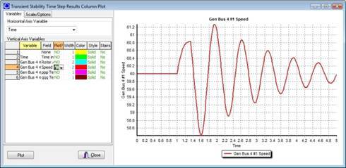
- When using the column plotting option to plot time points, time scale will now be in seconds if no difference between time points is greater than one minute.
- Modified the Time Step processing when using the SCOPF algorithm at each time step so that less messaging is sent to the Time Step dialog regarding the progress of the SCOPF solution. All the messaging to status edit boxes on the Time Step dialog was greatly slowing down the solution process.
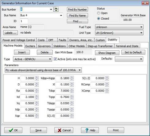
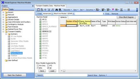
Transient Stability
- Transient Model Modification
- Added ability to specify whether to use the Runga-Kutta Order 2 (RK2) or Euler's method for the integration time step.
- Added a new option to specify the type of Exciter Saturation Model function. Choices are Quadratic, Scaled Quadratic, or Exponential.
- Transient Limit Monitoring: Modified the ability of Action To Take option to allow an option "Trip (Open) Device". The option will trip/open a device" if a monitoring violation occurs (this works for Buses, AC Lines, Generators, Loads, and DC Lines).
- Transient Plots
- Added the ability to add to a Plot a Title Block including an image logo, text, and a date.
- Added the ability to specify special strings such as "@CTGName" which will automatically determine an appropriate string to place in the Plot Title Block Memos, Axis Title captions, Chart Title, or Chart Footer. @CTGNAME will display the appropriate contingency name; @CASENAME will show the name of the case presently open; @BUILDDATE will show the Simulator patch build date; @DATETIME will show the present date and time; @DATE will show the present date; @TIME will show the present time.
- Added the ability to automatically save plot images during a transient stability run. The images will be saved in the same directory as the defined hard-drive storage directory.
- Transient Stability File Format Support
- Modified the loading of GE DYD files to also accept a file extension of "DYC". When loading a DYC file no prompt will appear asking about deleting existing stability models. The assumption is that it will append to existing models.
- Added the ability to read a "DYR file with options". When choosing this, you may specify a MCRE *.rwm file to split up generators, a MTRLD *.dat file to split up motors, a GNET *.idv file to disable generator models, and a BASEGEN *.dat to specify the Governor Response Limits flag for generators.
- Added the ability to load the MCRE, MTRLD, GNET, and BASEGEN files each separately if desired.
- When writing out a DYR file, we now automatically write out a GNET *.idv and a BASEGEN *.dat file. The filename and path used will be the same as for the DYR file, except "_GNET" and "_BASEGEN" are appended to the filenames.
- Transient Stability Contingency Definitions
- Added a new transient contingency event for "OPEN BUS" which opens all AC lines connected to a bus.
- Added ability to open only one end of a transmission branch in the transient contingency event.
- Added the ability to assign a model criteria to a transient contingency action. The action will then only be applied if the initial conditions meet the model criteria.
- Added ability to define transient contingency definitions based on an injection group. The only action allowed is Open and the user must specify whether to open generation, load or shunts. In addition they must specify the amount to open. When the contingency action is implemented the amount to open will be based on the initial condition of the device (not the transient condition), and devices will be opened in order of highest participation factor to lowest participation until at least the amount specified has been exceeded.
- Transient Stability Script Actions
- TSSolveAll - Solves all specified transient contingencies.
- TSSolve("ContingencyName", [StartTime, StopTime, StepSize]) - Solves only the specified transient contingency. StartTime, StopTime, and Stepsize are specified in seconds.
- TSWriteOptions("FileName", [opt1, opt2, ... opt5], KeyField) - Save the transient stability option settings to an auxiliary file specified by FileName. Opt1 through Opt5 should be set to YES or NO according to the specific option categories to save. These parameters are optional and the default is YES for any parameter not specified. opt1 - Save Dynamic Models; opt2 - Save Stability Options; opt3 - Save Stability Events; opt4 - Save Results Settings; opt5 - Save Plot Definitions; KeyField – Optional parameter. Primary, Secondary, or Label. If not specified set to Primary by default.
- TSCalculateSMIBEigenValues - Calculate single machine infinite bus eigenvalues. Initialization to the start time is always done before calculating eigenvalues.
- TSSaveTwoBusEquivalent("PWBFileName",[BUS busnum]) - Save the two bus equivalent model of a specified bus to a PWB file. Initialization to the start time is always done before saving the two bus equivalent. “PWBFileName� – name of the PWB file to which to save. Bus can be specified by number [BUS busnum], name/nominal kV combination [BUS "busname_nominalKV"], or label [BUS "buslabel"].
- TSLoadGE("FileName",GENCCYN) - Loads transient stability data stored in the GE DYD format. “FileName� – name of the DYD file to load. GENCCYN - YES or NO. Set to YES to split combined cycle units. Set to NO to leave them alone.
- TSLoadBPA("FileName") - Loads transient stability data stored in the BPA format. “FIleName� – name of the BPA file to load
- TSLoadPTI("FileName", "MCREfilename", "MTRLOfilename", "GNETfilename", "BASEGENfilename") - Loads transient stability data in the PTI format. “FileName� – name of the DYR file to load. This is NOT an optional field. All of the files listed after are optional. If not loading these particular files, specify an empty string, " ".
- Transient Stability Storage
- Added support for storing interface MW, Mvar, and MVA flows as part of the transient stability results.
- Added ability to store switched shunt, to store injection group MW and Mvar outputs, and to store multi-terminal DC record results in transient stability
- When choosing to store results to the Hard Drive, previously if no directory was specified to which results should be saved then results would not be saved to hard drive at all. Now if the directory is blank, Simulator will default to save data in the same directory as the case was loaded from. Note that if an invalid directory is specified it will offer the opportunity to create the directory or abort the run.