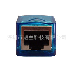
工程开发的装备,USB TO
SPI转接板,完全代替了烧录板,直接与笔记本USB连接,方便实用之极.有需要的工程朋友们速度与我联系.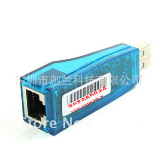
一. Introduction
This User
Guide describes the CSR USB-SPI Converter.
This product operates in the
temperature range -10C to 55
Custom firmware, stored in flash memory, takes
USB commands over SPI. The DSP:
Serialises the SPI
commands
Reads the SPI_MISO line
USB-SPI automatically reduces the SPI bit rate when it sees SPI data corruption.
二. Installing the Driver
Note:
The BlueSuite tools and driver are included on the
panying CD. However, you can always ess the
latest versions from the
Support website as described below:
1. With your browser go
2. Log in.
3. Navigate to the
PC Software Tools section.
4. Download and run the latest version of the
BlueSuite tools.
5. When selecting components from the Setup window ensure
that the DLL and drivers to allow SPI communication with the chip option is
selected:
6. Connect the USB-SPI to the PC. You might briefly see aFound New
Hardware message in the task bar.
A Found New Hardware Wizard window
appears:
7. Select No, not this time and press Next
8. Select Install
from a list or specific location (Advanced) and press Next
9. Select Include
this location in the search
10. Set the path name in the Browse field to the
BlueSuite drivers directory and press Next
If you used the default install
path this is: C:\\program Files\\CSR\\BlueSuite\\drivers
11. On the Hardware
Install window press Continue Anyway
The drivers are now installed.
12. Press Finish
13. To check the installation from Windows, look at the
Device Manager directory. USB-SPI should be listed.
三. Using the USB-SPI Converter
3.1 Using USB-SPI with BlueFlash
BlueFlash programs the
flash memory of CSR ICs:
1. Ensure that the USB-SPI is connected.
2. Run
BlueFlash.exe from the installation CD.
3. Select the USB-SPI from the
drop-down menu.
4. Press Stop Processor.
The LEDs sequence on the body
of the USB-SPI.
Note:
You may see a XAP or SPI error message. This means
that BlueFlash could not detect a CSR IC
attached to the CAT5 (SPI) lead.
Check that the USB-SPI is connected and that power is supplied
to the target
board.
3.2 Using USB-SPIwith PSTool
PSTool changes non-volatile
settings in the flash memory or EEPROM of a CSR IC. To use USB-SPI with
PSTool:
1. Ensure that the USB-SPI is connected.
2. Run
PSTool.exe from the installation CD.
3. Select the USB-SPI from the
drop-down menu.
4. Press OK. If you do not have a CSR IC with valid
firmware attached, PSTool fails. The LEDs do flash however.
5. Press Abort
on the error dialogue to exit PSTool.
3.3 Connecting USB-SPI to a
Casira
The Casira Development Kit uses an IDC connector for the SPI
interface. Use the adaptor, shown in
Figure 3.1, to plug the CAT5 lead into
a Casira.
四. USB-SPI Hardware
4.1 SPI Connector Pins
Figure 4.1 shows the SPI
connector pins 8-1.