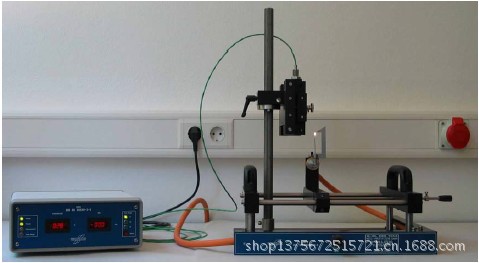
供应IEC60695-2-2针焰测试仪德国原装进口针焰测试仪
应用领域:主要用于模拟技术评定设备内部由于某种故障条件所造成的小火焰的着火危险性试验的专业仪器。适用于电子电工的设备及其部件和元件的着火危险性的测定,也适用于固体电气绝缘材料或其它可燃材料的着火危险性。
Needle Flame Tester in accordance with DIN EN 60695-2-2
Model:NPG
The tester serves to test with a needle flame, to simulate the impact of small flames, that might occur by faulty working conditions of the product, to evaluate the risk of fire by means of a imitating test procedure. The test flame is the source of fire impacting on the sample for a certain period of time. The confirmation of the flame is conducted by the flame test arrangement and the calibration device. The temperature on the copper block is determined using a sheathed thermocouple type K (class 1) in accordance with IEC 60584-2. The calibration device is able to monitor the space of time from 100℃ to 700℃ and calculate the average time from three time measurements. The calibration device provides a digital and an analogical temperature output the time can be determined externally from.
Set-Up
Connect the calibration device to your power supply and the thermocouple on the back side of the calibration device. Connect the needle flame burner to the gas supply. The needle flame burner needs to be operated at 50 mbar. Connect the thermocouple to calibration device at the back side of the housing (picture 1).
Conducting the Flame Confirmation
Mount the thermocouple with its support to the stand. Adjust carefully on the height adjustment of the stand the distance in between copper block and burner pipe to 6 mm (picture 3). To do that the burner has to be in a vertical position. Fix its position so that the needle flame burner is below the copper block by adjusting the stop on the guiding rod. That way the position for the calibration procedure is fixed. After that move the needle flame burner to its initial position to the right side of the tester. Ignite the burner and turn on the calibration device. The flame height template has to be mounted (picture 6) so that the lower edge of the template’s sinking is on the same level as the shoulder of the needle flame burner (diameter 6 mm).Set the height of flame according to the standard and height
adjustment template (picture 2). The gas flow to the needle flame burner can be adjusted by the fine adjustment valve on the front side of the tester (picture 4). When the calibration device is in working condition move the needle flame burner carefully below the copper block and heat it up (picture 5). Then the burner must not be moved anymore or the flame disturbed by ambient air flows. After the temperature has risen up to 700℃ the measurement is completed and the burner can be put in its initial position. Before running a new test let the copper block cool down below 50℃ without any external help.
Running a Test
Through a brass milling wheel the needle burner can be turnt from a vertical position into a 45 ° position (picture 7). Mount the sample and tighten it by adjusting the stops (picture 8). Align the needle burner according to your test arrangement to the sample and set the stops on the guiding rod. Move the burner towards the sample and let the sample being exposed to the flame for the determined space of time (picture 9).


