EMG-EKL3.2面板型接地短路故障指示器
说明书及安装手册
一、 概述
目前高压线缆的大量使用,使得线缆的故障率也相应的增加。特别在多条线缆供电系统中,如出现越级保护跳闸时,将难以判断具体的故障电缆,有时甚至要将所有电缆全部拆除做耐压试验后才能正确判断故障电缆。其工作量大、实施困难、是难以想象的。对此有必要设计一种新型的检测设备,实时的对各供电回路进行监控。当线路发生故障时,能提示或直接显示故障电缆。对提高工作效率,迅速恢复供电有着十分重要的意义。
二、 主要功能
1、短路电流报警指示:短路电流传感器在工作中对正在运行的高压电缆进行在线检测,当线路电流达到或超过短路电流的整定值时(可根据用户要求在出厂前进行整定),短路传感器发出报警信号通过光纤传输到主机,主机接收到此信号后,产生相应的报警指示信号,同时可将信号发送到主控系统。
2、接地报警指示:本系统采用接地传感器检测用户电缆的接地电流,当接地线路中电流达到或超过接地电流启动报警值时(可根据用户要求在出厂前进行整定),接地传感器发出报警信号传到主机,主机接收到此信号后,产生相应的报警指示信号,同时可将信号发送到主控系统。
3、自动复位系统:当指示器发出报警信号后,如果无人工复位,则指示器将在设定的复位时间内自动复位。
4、人工复位:当指示器产生报警后,可通过按下指示器主机面板上的清除按钮进行解除报警进行人工复位。
5、测试:本系统可通过面板上的清除按钮进行自检工作,以检测本机的功能。连续按下面板上的清除按钮2秒钟,本机进入自检状态,所有面板上的指示灯闪亮,输出继电器吸合,说明工作状态正常。
6、自动化:指示器产生指示报警信号后,可将报警信号输出远传。也可接收远方的复位信号,对指示器进行远方复位操作。
三、 显示原理
其短路部分原理与翻牌显示原理相同。接地部分检测线路零序电流作为判断依据,显示方式是通过面板上的指示灯来完成的。当电缆系统出现故障时,如果面板上的接地指示灯亮,表明电缆系统发生了接地故障;如果面板上的某两相短路指示灯亮,表明这两相发生了短路故障。
四、 适用范围:各种型式的环网开关柜
五、 技术参数:
l 适用电压等级: 6-35KV
l 适用负荷: 0-600A
l 适用导线电流: I≤1000A
l 适用导线线径: 25mm2≤d≤400mm2
l 动作响应时间: 0.06S≤T≤3S
l 静态功耗: ≤10uw
l 动作复位时间: 10S、6、12、24、48小时可选
l 使用环境温度: -400C≤T≤+750C
l 动作次数: >4000次
l 接地故障启动值: ≥150A 误差±10%;出厂设定为800A
l 短路故障启动值: 3A~2000A 误差±10% 出厂设定为20A
六、 外形尺寸及端子接线图
开口尺寸:91.5mm(公差:+0.3)X43.5mm(公差:+0.3)
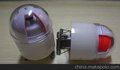
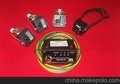
七、 组成:主机一个,短路传感器三个,接地传感器一个,光纤四根。

八、 安装方法及安装示意图
安装步骤如下:
1、指示器的主机安装在配电柜的前面板上。


2、将三个短路电流传感器分别安装在电缆的A、B、C三相上,必须紧固地套接在被检测的线路上。


3、将接地电流传感器安装在三相电缆的三岔口下端,其磁轭应该将三相包围起来。
4、安装后的结构图。

九、 主机与电流传感器的接线连接
在主机背面可见一圆形三孔栓(L1、L2、L3)与一个单孔栓,及用以检测故障的电流传感器数据输出信号与主机链接的接口。具体安装办法如下:
1、将对应A相的短路电流传感器与L1相链接
2、将对应B相的短路电流传感器与L2相链接
3、将对应C相的短路电流传感器与L3相链接
安装时先将各接头处的光纤帽拧松,将光纤线插入光纤接口内,再拧紧光纤帽即可(三孔栓上用来遮挡光纤接口的黑色圆形塑料片在安装前需拧下光纤帽将其去掉)。
注:在安装过程中,主机接收部位的光敏管可能感光,导致面板上的指示灯闪亮,此时需将指示器进行手动复位。复位办法:按住面板上的“复位/检测”按钮2秒钟以上,所有指示灯开如闪亮即可。
十、 注意事项
1、清除故障时,按复位按钮2秒钟就可清除;
2、更换电池后要按复位按钮,指示器就进入正常状态。
ASSEMBLING INSTRUCTION
Earth Fault and Short Circuit Indicator Type EKL3.2
(Panel instrument)
Descrition
The earth fault and shot circuit indicator consists of:
l 1 pc reading instrument (panel instrument)
l 3 pcs sensors for detecting short circuit current
l 4 pcs linght cable
l 1 pc sensor for observing the sum current
l 1 pc flashing lamp (optional)
Installation of the reading instrument
The Earth Fault and Short Circuit Indicator is designed for panel installation .The necessary dimensions of the cutout are 91.5+0,6x44.5+0,6mm ( refer to figure 2 ) .Before sliding in the instrument , the electrical connections can be accomplished .The housing is slded into the opening and pushed with a light pressure up to stop position .Springs ( figure l ) serve to keep the reading instrument in its position .
Installation of the light cable
The sensor which is installed on the cable,is connected to
the reading instrument via light cable.Therefore the sensor
of core L 1has to be connected with the terminal L1 on the
back of the reading instrument.(The endings of the light
cables have to be pushed into the pick-up openings up to
stop position.)The same has to be done with the Sensors L2,
L3 and the earth fault sensor 14(figure 3).
Power supply
The power supply is performed via a 3.6 V lithium
battery.For exchanging the battery,a screw cap
on the front side of the indication housing must
be removed by turning it left.The battery must be
taken out and replaced by a new one.(With the
supply via lithium battery,the 230 VAC are only
connected in case the erath fault and short circuit
indicator type EK shall be reset also via recovering
voltage of the net.)
Electric connection
Depending one the version,the electrical connection has to be done according to the designations in figure 3.
Terminals without any marking(NC)are without any function.In principle,the information indicated on the reading instrument is valid.
Setting the display time
The time of displaying after a short circuit or earth is
adjustable.
There are three times to choose.The standard reste times are:1-2
-4h(other values are possible).The adjustment of the reset times
will be done by a rotaryswitch.The rotary switche is on the front
side of the indicator in the left top corner.The possible switch
positions are shown if figure 4.
Setting the operating points for short circuit
The adjustment of the operating points of the earth fault and shore circuit indicator indicator type EKL4 is done at the sensors.Three different operating points can be adjusted.The operating points are adjusted with a rotary switch at the front side of the sensor.The adjustable operating points are indicated on the front side of the sen