


。


1. GENERAL INFORMATION
Model 10/100M-E1 is a single port E1 with Ethernet Bridging that provides high-speed LAN-to-WAN connectivity. Plugging directly into the 10/100Base-T port of a hub or LAN switch, the 10/100M-E1 provides E1 access at connection data rates of 2.048 Mbps. The10/100M-E1 is an excellent choice for internet access as well as LAN-to-LAN services.
.2.PRODUCT CHARACTERISTIC
Based on self-copyright IC.
Ethernet port 10/100M half/full duplex self adaptable, supporting VLAN.
RJ45 interface supports AUTO-MDIX.
Provides 2 clock types: E1 master clock, E1 line clock.
Has the function of pseudo-random code testing, convenient for opening of the circuit, and can be used as an error code instrument.
Have three LoopBack Modes: E1 interface LoopBack (ANA)、LAN interface LoopBack (DIG)、command the remote LAN interface LoopBack (REM) .
75-ohm dual coax and 120-ohm twisted-pair G.703 connections provided, and support 75ohm/120ohm adapt ;
With abundant presentation function of Ethernet data, can detect real-time data communication status.
Can realize SNMP management in our chassis installation
3.ENVIRONMENT REQUIREMENT
The temperature requirement is not very strict, the device can be working well under terrible environment.
working temperature: 0°C - 50°C
relative humidity: 95%(without coagulation)
No erosive and impregnant gas, no rising dust, no strong magnetic field disturbing
3.1 Power
Adapting module power, voltage range can be wide, with strong ant-jamming function.
With good insulation, stable working status is available
power: -48V type, input voltage: -36V~-72V
power: 220V type, input voltage: 175V~250V
3.2 Power consumption
Total power consumption: <5W
3.3 E1 Interface
Line Rate: 2.048Mbps±50ppm
Line Code : HDB3
Interface Standard: ITU-T G.703
E1 Impedance : 75Ω(unbalance) and 120Ω(balance)
Connections : dual coax and 120-ohm twisted-pair (RJ45)
Jitter tolerance : finer than G.742 and G.823
3.4 10/100Base-T Interface
Rate: 10/100M, full/duplex auto-negotiation
Protocol: Support IEEE 802.3, IEEE 802.1Q (VLAN)
MAC Address Entiries: 4096 Entiries
Total Memory Sizes: 64MBits SDRAM
Physical interface: RJ45, support AUTO-MDIX
4. DIMENSIONS
216(W) × 140 (L) x 31(H) mm
5. CONFIGURATION AND OPERATION
Note:
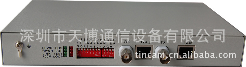
TX —— E1 75Ω unbalance, Transmit BNC Interface
RX —— E1 75Ω unbalance, Receive BNC Interface
LAN —— 10/100Base-T Interface, RJ45
120Ω/E1 —— FE1 120Ω Balance Interface, RJ45
5.2 LED Indicator
There are 8 indicator LEDs.
LOS——Active Red, signifying E1 signal Lost
LOF——Active Red, signifying E1 Frame lost
TEST——Active Red, signifying the device is on test status
LOOP——Active Red, signifying there is loop on the network.
LPWR——Active Green, signifying the local device is power on.
RPWR——Active Green, signifying the remote device is power on.
LINK——Active Green, signifying a valid 10/100BaseT connection.
100M——Active Green, signifying the rate is 100M.
Note:
LOS on & RPWR off: the remote device is power off.
LOS on & RPWR on: E1 line is cut off.
LOS off & RPWR off: normal.
Caution: There may be some mistakes when all indicating lights winks, (except for the PWR light)
both of the device are on the status of line clock;
both of the device are on the status of master clock while the rate setting is different;
the test key connecting are incorrect which cause into the dead cycle.
5.3 Four-DIP switch for loop back test
There is a four-DIP switch, defined as follows.
ANA: For E1 Interface local loop to check whether local device and its connected circuit are correct or not.
DIG: For 10/100BASE-T Local loop to check the opposite device and optical circuit
REM: Invalidate for unframing.
PAT: Reserved. Under the test mode, the device will sent the testing data real time and detecting if there is any loop on the network.
Note:
When the test LED on, the normal communication will be terminated.
The LOOP LED will on if there is any loopback on the network:
ANA on: local LOOP on.
DIG on: remote LOOP on.
REM on: local loop on.
5.4 Eight-DIP Switch on the panel
There is a 8-DIP switch to set the device.
5.5 Description of E1 and LAN connector
E1 connector
75Ω/RX: 75Ω unbalance receive in
75Ω/TX: 75Ω unbalance transmit out
120ΩFE1: 120Ω balance receive and transmit
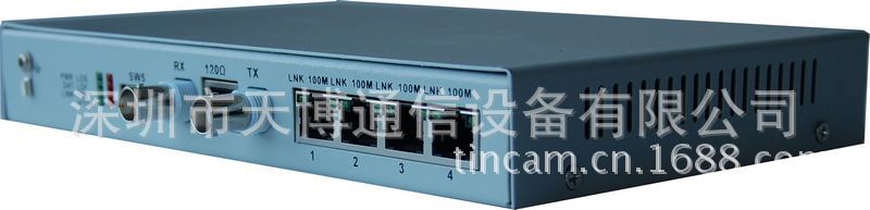
LAN Interface
10/100M RJ45 on the back panel support AUTO-MDIX(cross and straight connection through auto-negotiation). The connection way for cross and straight connection are shown as below.
5.6 Power Installing
Power of AC220V/ DC-48V is suitable for the device. If the power of DC-48V is used, the positive and negative terminal can be optional because there is the self-test circuit for the polarity inside the optical modem.
'