1. Key Parameters
Item | Name | Description | |||
1 | Service
| H2S
| |||
2 | Design temperature
| -10℃~50℃ | |||
3 | Design wind load
| Max operation windspeed:36m/s; Max towing wind speed:51m/s | |||
4 | Burner Boom Quantity
| 1 set
| |||
5 | Burner Head Quantity (1 set boom)
| 3ea oil burner head
| |||
3ea diesel burner head
| |||||
1ea natural gas burner
| |||||
6 | Oil burning capacity
| 4000BPD/each head
| |||
7 | Ignition System
| electric igniters
| |||
8 | Electrical Requirement
| 220V,1PH,60Hz
| |||
9 | PIPE Design Codes
| ANSI B31.3,NACE(MR 0175) | |||
10 | Design life 设计寿命 | Burner head | 15years, | ||
Boom | 20years, | ||||
11 | Boom length
| 21.3m(from pivot centre to tip)
| |||
12 | Burner Platform length
| 3.85m 3.85 | |||
13 | Rotation direction
| Horizontal to vertical
| |||
14 | 1 Set Total Weight
| 9.0
| Burner Boom | 8.5 t | |
Foundation etc.
| 0.5t | ||||
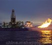
2. Supply Scope of Burner Boom for each Rig are as below table:
Item
| Working pressure
| Size(L×W×H)m
| Weight (Ton)
| Location | Qly
| Interface
| Others
|
Burner arm Trestle
| NA | 21300×875×875 | 6.0T | Specified location on the platform
| 1 | Connected with foundation,
| Include handrail |
Internal working lines and fittings | NA |
|
| Inside trestle
| 1 | Inlet union(female) Outlet union (male) |
|
1 Foundation | NA |
| 0.5T | On the main deck
| 2 | Welded on the deck
|
|
Lifting pulley | NA |
|
| On the Kingpost
| 5 | Welded on the Kingpost
| The spec. are determined by detailed design |
wire ropes and shackles |
|
|
| Using on burner boom | 2 | Connecting between burner boom and deck | The spec. are determined by detailed design |
High-pressure crude oil hose
| 1500 Psi | 4”-3” |
|
| 2 | Inlet FIG 3”602 union(female) Outlet FIG 3”602 union (male) | Between platform and burning boom
|
High-pressure nature gas hose
| 1500 Psi | 6’’-4” |
|
| 2 | Inlet FIG 4”602 union(female) Outlet FIG 4”206 union (male) | Between platform and burning boom在 |
Diesel hose
| 150 Psi | 2” |
|
| 2 | Inlet FIG 2”602 union(female) Outlet FIG 2”602 union (male) | Between platform and burning boom
|
Air hose
| 150Psi | 4”-3’’ |
|
| 2 | Inlet FIG 3”602 union(female) Outlet FIG3”602union (male) | Between platform and burning boom
|
Air hose
| 150Psi | 2” |
|
| 2 | Inlet FIG 2”602 union(female) Outlet FIG 2”602union (male) | Between platform and burning boom
|
Seawater hose
| 1450 Psi | 3’’ |
|
| 2 | Inlet FIG 3”602 union(female) Outlet FIG 3”602union (male) | Between platform and burning boom
|
Liquefied gas hose
| 150 Psi | 1/2” |
| Inside trestle
| 2 | 1/2” quick connector | Between platform and burning boom在 |
Liquefied gas tank
| 120Psi | 35L | 15kg | On the deck
| 2 | Connect inlet of liquefied gas hose |
|
Burner
|
| 3800x2290x2000 | 2.5 | At trestle top
| 2 | Connect with all routes of pipeline on the trestle
| Supply thermal radiation report |
Igniting Device
|
| IP56 |
| At trestle end
| 2 | Cable-high-pressure igniter ---ignition lead/metal lead-protecting tube---spark plug | Only supply the socket by shipyard |