Electrical Characteristics of SL37408 Series:
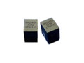
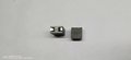
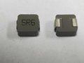
3. Mechanical Dimension of SL37408 Series:
Notes:
1. Open Circuit Inductance (OCL) test condition: 100KHz,0.1Vrms,0Adc at 25Ԩ .
2. L @ Isat and L @ Irms Test condition: 100KHz,1.0Vrms (Ta=25Ԩ ).
3. The nominal DCR is measured from point "a" to point "b", as shown above on the mechanical drawing (Ta=25Ԩ ).
4. Isat1 , Isat2 & Isat3 : DC current that will cause inductance to drop approximately by 20%.
5. Irms: DC current for an approximate temperature rise of 40Ԩ without core loss. Derating is necessary for AC currents. PCB
pad layout, trace thickness and width, air-flow and proximity of other heat generating components will affect the temperature rise.
6. It is recommended the part temperature not exceed 130°C under worst case operating conditions as verified in the end application.
ITG Part Number
OCL 1
L @ Isat1 2
DCR 3
Isat1 4
Isat2 4
Isat3 4
Irms 5
Dim. C
(nH) (nH) (mΩ) (A) (A) (A) (A) (mm)
± 10% Min.
± 5.0% @25℃ @45℃ @100℃ @25℃
Max.
SL37408A-R10KHF 100.00 72.00 0.23 120.00 115.00 107.00 60.00 10.20
SL37408A-R12KHF 120.00 86.40 0.23 98.00 94.00 87.00 60.00 10.00
SL37408A-R15KHF 150.00 108.00 0.23 78.00 75.00 69.00 60.00 10.00
SL37408A-R18KHF 180.00 129.60 0.23 64.00 61.00 58.00 60.00 10.00
SL37408A-R22KHF 220.00 158.40 0.23 52.00 49.00 46.00 60.00 10.00
SL37408A-R27KHF 270.00 194.40 0.23 42.00 39.00 37.00 60.00 10.00
SL37408A-R30KHF 300.00 216.00 0.23 37.00 34.00 31.00 60.00 10.00
SL37408A-R33KHF 330.00 237.60 0.23 33.00 30.00 27.00 60.00 10.00
Technical Data 4340
Effective June 2017
www.eaton.com/electronics
Packaging information - mm
Dimensions- mm
1 Open Circuit Inductance (OCL) Test Parameters: 100kHz, 0.10Vrms, 0.0Adc
2 Full Load Inductance (FLL) Test Parameters: 100kHz, 0.1Vrms, Isat1
3 Irms: DC current for an approximate temperature rise of 40°C without core loss. Derating is
necessary for AC currents. PCB pad layout, trace thickness and width, air-flow and proximity of
other heat generating components will affect the temperature rise. It is recommended the part
temperature not exceed 125°C under worst case operating conditions verified in the end
application.
4 Isat1: Peak current for approximately 20% rolloff at +25°C.
5 Isat2: Peak current for approximately 20% rolloff at +125°C.
6 K-factor: Used to determine Bp-p for core loss (see graph). Bp-p = K * L * ΔI * 10-3, Bp-p : (Gauss),
K: (K-factor from table), L: (inductance in nH), ΔI (peak-to-peak ripple current in amps).
7 Part Number Definition: FP0805Rx-Rxx-R
• Rx is the DCR indicator
• FP0805 = Product code and size
• Rxx= Inductance value in μH, R = decimal point • “-R” suffix = RoHS compliant
Product Specifications
Part Number7
OCL1 ± 10% (nH) FLL2 Min. (nH) Irms
3 (Amps) Isat14 @ 25°C (Amps) Isat25 @ 125°C (Amps) DCR (mΩ) @ 20°C K-factor6
FP0805R1-R03-R 32
23
110
95
823.6
FP0805R1-R06-R 58
42
83
61
823.6
FP0805R1-R07-R 72
52
65
67
49
0.17 ± 17% 823.6
FP0805R1-R10-R 100
72
50
35
823.6
FP0805R1-R20-R 200
144
20
16
823.6