专业POE 电源模组供应 48V 0.5A

深圳市丰润达科技有限公司
中国 深圳
产品属性
图文详情
品牌推荐
品牌/型号
PSKY/PSKY-POE-036
调制方式
脉冲宽度调制PWM式
输入电压
48(V)V
输出功率
15/30(W)W
输出电压
12/9/5/3.3(V)V
产品认证
UL
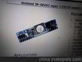
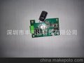
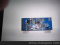
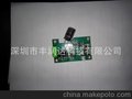
Powered Device of PoE(PD MODULE) PSKY-POE-011. Features:*IEEE 802.3 standard-compliant solution, including pre-standard(legacy) PoE support* Highly-integrated compact solution PCB* Support transient surge protection that defined in IEC60060 as a 1000V impulse* Designed for non-isolated topologies* Comprehensive protection circuitry- Transient overvoltage protection- Undervoltage lockout
- Overload protection- Thermal shutdown protection- Current limiting protection- Short circuit protection* Support classification from 0 to 4(HW Default is Class 0)* Very small PCB size:57*14mm 2. Applications:*Voice over IP telephones* Wireless access points* Security cameras* Point-of-sale terminals* Low-power network switch 3. Electrical Specifications: Input Voltage of CT1 to CT236 to 57VInput Voltage of SP1 to SP236 to 57VOutput Voltage5V (Can ADJ for customer)Maximum Output Power(Can ADJ for customer)<3.84W<6.49W<12.95W<17WClass0 (Can ADJ for customer)Ambient Operating Temperature-20~65ºCAmbient Storage Temperature-40ºC~85ºC Table
1. Class Resistor Values
4. Pin Descriptions: Pin # Name Description1CT1TX Input (2). This input pin is used in conjunction with VA1 and connects to the centre tap of the transformer connected to pins 3 & 6 of the RJ45 connector (TX) - it is not polarity sensitive.2CT2RX Input (1). This input pin is used in conjunction with VA2 and connects to the centre tap of the transformer connected to pins 1 & 2 of the RJ45 connector (RX) - it is not polarity sensitive.3SP1Direct Input (1). This input pin is used in conjunction with VB2 and connects to pin 4 & 5 of the RJ45 connector.4SP2Direct Input (2). This input pin is used in conjunction with VB1 and connects to pin 7 & 8 of the RJ45 connector.5CP1Class Programming (1).Connect an external resistor to CP2 will change the current class of the module. With no resistor fitted the Ag8000 will default to Class 0.6CP2Class Programming (2).Connect an external resistor to CP1 will change the current class of the module. With no resistor fitted the Ag8000 will default to Class 0.7VOUT Negative DC Output.This pin provides the regulated output from the DC/DC converter.8VOUT Positive DC Output.This pin provides the regulated output from the DC/DC converter.9ADJOutput Adjust.The output voltage can be adjusted from is nominal value, by connecting an external resistor from this pin to either the VDC pin or the -VDC pin.10NCInternal Connection.Do not connect to this pin.
5. CircuityFunctional Description
INPUT: The PD MODULE has two internal bridge rectifiers inside. connected to the SP1-SP2 and the CT1-CT2 inputs. This allows the PD MODULE to be compatible with equipment that use the different power options, see Figure: Typical System Diagram. It is important that the PSE does not apply power to the CT and SP outputs at the same time (Refer to IEEE802.3af for more information). PD Signature: When the PD MODULE is connected to the Cat 5e cable, it will automatically present a Powered Device (PD) signature to the Power Sourcing Equipment (PSE) or Midspan Equipment, when requested. The equipment will then recognise that a powered device is connected to that line and supply power. 6. Recommended External Circuity: 7. Package:
联系资料: 丰天国际有限公司
冯生
13510096437