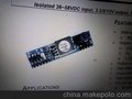
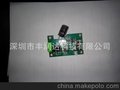
PSKY-AAT-12V module
1.Features:
? *IEEE 802.3 standard-compliant solution,including pre-standard(legarcy)PoE support
? *Highly-integrated compact solution PCB
? *Support transient surge protection that defined in IEC60060 as a 1000V impulse
? *Comprehensive protection circuitry
? -Transient overvoltage protection
? -Undervoltage lockout
? -Overload protection
? -Thermal shutdown protection
? -Current limiting protection
? -Short circuit protection
? *Support classification from 0 to 4(HW Default is Class 0)
? *Very small PCB size:62*27*18(mm)
2.Application:
? *Voice over IP teltphones
? *Wireless access points
? *Security cameras
? *Point-of-sale terminals
? *Low-power network switch
? *Wireless access point
3.Electrical Specifications:
Input Voltage of SP1 to SP2 36 to 57V
Output Voltage 12V
Maximum Output Power
(Can ADJ for PCBA)
<3.84W
<6.49W
<12.95W
<25.5W
Class 0 (Can ADJ for PCBA)
Ambient Storage Temperature -40∽85℃
Table 1.Class Resistor Value
Class Usage Power Leverls Nominal Class
Current
RCL Resistor
(1%,1/16W)
0 Default 0.44 W to 12.95 W 0-4mA 615Ω
1 Optional 0.44 W to 3.94 W 9-12mA 117Ω
2 Optional 3.84 W to 6.49 W 17-20mA 66.5Ω
3 Optional 6.49 W to 12.95 W 26-30mA 43.7Ω
4 Reserved 12.95 W to 25.5 W 36-44mA 30.9Ω
4.Pin Description:
Pin # Name Description
1 SP1 Direct Input(1).This input pin is used in conjunction with VB2 and connects to
pin 4 & 5 of the RJ45 connector.
2 SP2 Direct Input(2).This input pin is used in conjunction with VB2 and connects to
pin 7 & 8 of the RJ45 connector.
3 CT1
TX Input (2). This input pin is used in conjunction with VA1 and connects to
the centre tap of the transformer connected to pins 3 & 6 of the RJ45
connector (TX) - it is not polarity sensitive.
4 CT2
RX Input (1). This input pin is used in conjunction with VA2 and connects to
the centre tap of the transformer connected to pins 1 & 2 of the RJ45
connector (RX) - it is not polarity sensitive.
5 CP1 Class programming(1).Connect an external resistor to CP2 will
change the current class of the module.With no resistor fitted
the Ag8000 will default to Class 0.
6 CP2 Class Programming (2).Connect an external resistor to CP1 will
shange the current class of the module.With no resistor fitted
the Ag8000 will default to Class 0.
7 Vout- Negative DC Output.This pin provides the regulated output from the DC/DC
DATASHEETV1.0 Power-Over-Ethernet Module
converter.
8 Vout- Negative DC Output.This pin provides the regulated output from the DC/DC
converter.
9 Vout+ Positive DC Output.This pin provides the regulated output from the DC/DC
converter.
10 Vout+ Positive DC Output.This pin provides the regulated output from the DC/DC
converter.
11 NC
12 NC
Notes: Pin7.Pin8 can change to one Pin
Pin9.pin10 can be change to one Pin